%$6,&6(77,1*2)7+(7+5
'+:352'8&7,21:,7+$'(5,9$7,219$/9(9,$7+(/*0
Only valid for version THR 10-100 CS
D.h.w. production is carried out with a selector valve
and a d.h.w. sensor on the module(s) controlled by
the LGMs. This makes it possible to reach a maxi-
mum heating power of 50 kW for each tank. Each
LGM manages its own d.h.w. production.
+\GUDXOLFFRQQHFWLRQ
The THR 10-100 CS was originally equipped with
two selector valves which make it possible to con-
nect two d.h.w. production systems (1 on the right,
the other on the left).
$QH[SDQVLRQWDQNDQGD ZDWHUILOOLQJ
V\VWHPIRUWKHLQVWDOODWLRQPXVWEHSUR
YLGHG RQ WKH GKZ RXWOHWV RI WKH
7+5 &6VHHSDUDJUDSKVHF
WLRQ,9,167$//$7,21
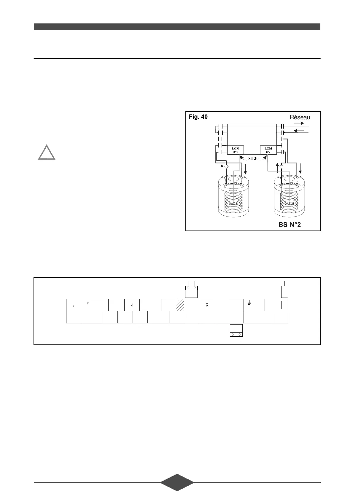
(OHFWULFDOFRQQHFWLRQ
The selector valves were originally connected to the
LGMs. The d.h.w. sensors must be connected to the
ST 30 terminals of the relevant LGMs with the pro-
vided connectors and must be inserted into each
d.h.w. production system.
!
7+5&6
%61
/*0
Q
/*0
Q
67
%61
Réseau
)LJ
N L
ignition
Transformer
Transformer
15 - 24 V
overheat
safety
thermostat
2220 23 25 26
13
29
Room
thermostat
Gas
valve
Shunt
(2-wires)
Selector
valve
Heating
circuit
Ionisation
probe
Boiler
sensor
Fan
Hot water
sensor
outside
sensor
Control
module
Room
sensor
Power supply
Transformer
230 V
)LJ
 Loading...