23(5$7,1*)$8/76
23(5$7,1*)$8/762)5(*8/$72559$
2QFHWKHIDXOWKDVEHHQHOLPLQDWHGWKH
(UHUURUPHVVDJH RQWKH59$PD\
WDNHWR PLQXWHVWRGLVDSSHDUDF
FRUGLQJWRWKHW\SHRIIDXOW
2SHUDWLQJIDXOWV
7KHGLVSOD\RIWKHUHJXODWRUUHPDLQVEODQNQR
GLVSOD\
• Check whether the main heating switch is se-
lected .
• Check the heating circuit’s fuses.
• Check the wiring.
7KHWLPHGLVSOD\HGE\WKHUHJXODWRULVZURQJ
• Adjust the regulator’s clock (programming
line 1).
• Adjust the master regulator’s clock (if need be).
$Q/*0GRHVQRWDFWLYDWH
• Should this LGM really be in service?
Check the boilers’ cascade strategy, timing at
selection, timing at deselection).
• Si nécessaire, déverrouiller le LGM.
• Check the control thermostat (TR) and the sa-
fety thermostat (STB).
• Check the LGM’s wiring and fuse.
• Check the communication link with the LGM
(line 54).
• Check the wiring of the cascade temperature
sensors (input test, line 52).
$SXPSGRHVQRWRSHUDWH
• Check that the displayed type of installation is
correct (line 53).
• Is the pump correctly defined? (line 95)
• Check the pump’s wiring and the fuses (output
test, line 51).
• Check the sensors’ wiring (input test, line 52).
7KH'+:LVQRWKHDWHG
• Check that the DHW button is ’ON’
• Check the Domestic Hot Water temperature
setting.
• Check that the Domestic Hot Water load is re-
leased.
• Check the wiring and the fuses of the domestic
hot water load pump (output test, line 51).
• Check the Domestic Hot Water sensor’s wiring
(input test, line 52).
• Check the setting of the control thermostat
(TR). It must be greater than TKmax.
7KHURRPWHPSHUDWXUHGRHVQRWPDWFKWKHGH
VLUHGYDOXH
• Does the setting displayed on the control knob
match the desired value ? (Regulator control
knob, possibly on the room sensor.)
• Is the desired regime displayed?
• Do the displayed weekday, the time and the
heating programme coincide? (lines 1-11).
• Is the heating characteristic’s slope correctly
set (line 17)?
• Check the wiring of the outdoor sensor
(line 52).
• Was the room temperature comfort setting set
with the translation of the heating characteris-
tic (line 100)?
/HPHVVDJHGHGpIDXW³(5´DSSDUDvWVXUODIIL
FKDJH
• Check that the LGM’s Summer/Winter potenti-
ometer is on the Winter position
.
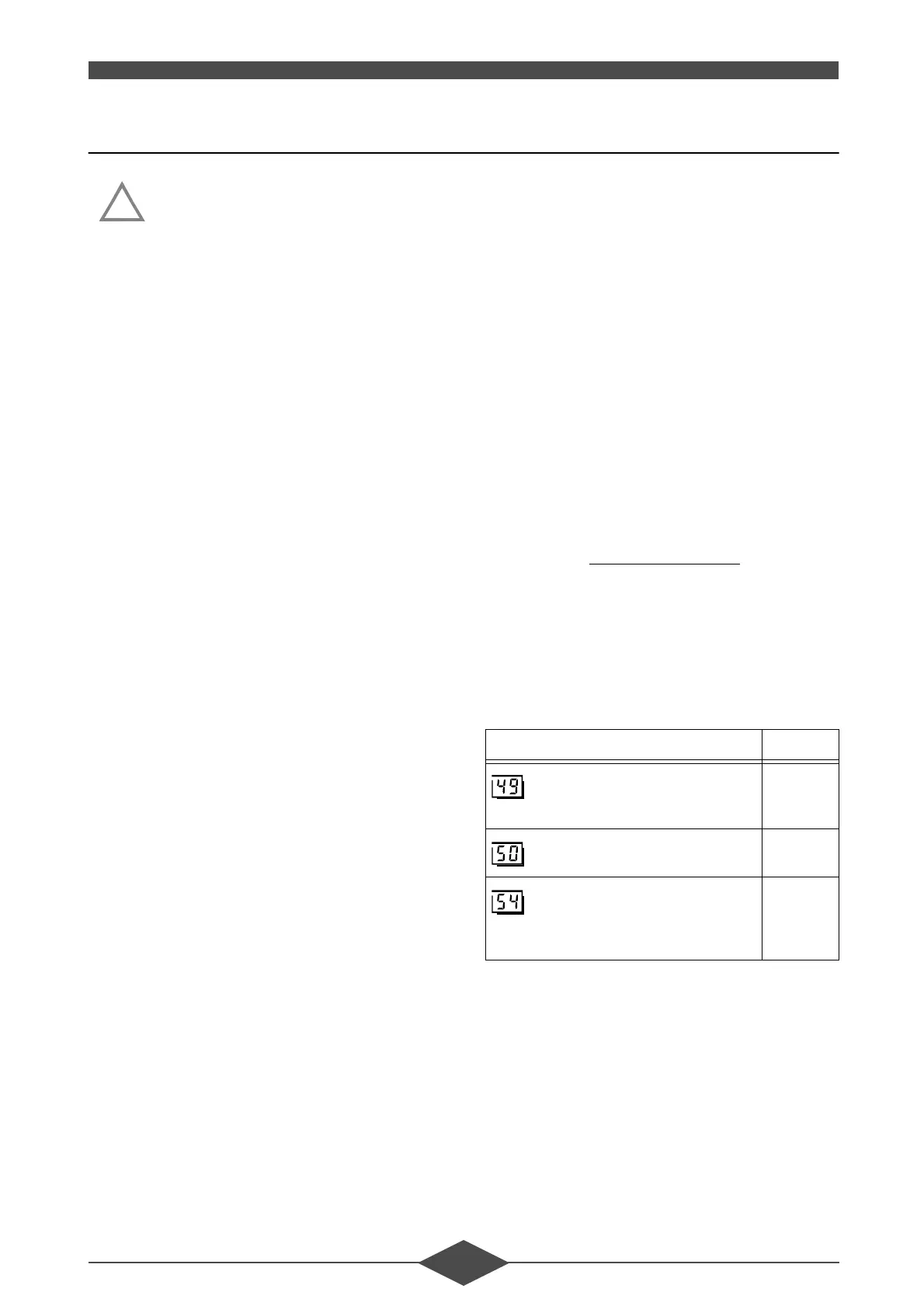
• Select programming lines 49, 50 and 54. The
error code and the address where the error
took place are displayed there. Paragraph 2.2
- below lists the possible error codes and their
meaning.
The displays of these parameters must be
those of the table below.
!
59$UHJXODWRUSDUDPHWHUV 'LVSOD\
: display of the BMU (LGM) error
codes
- - -
: display of errors
vide
: display of PPS communication
selection of the PPS addresses
using the +/- buttons
4 102
5 102
 Loading...