EasyManua.ls Logo

Gigabyte GA-H81M-H User Manual

Gigabyte GA-H81M-H
31 pages
To Next Page IconTo Next Page
To Previous Page IconTo Previous Page
Page #14 background imageLoading...
Page #14 background image
- 14 -
8) F_PANEL (Front Panel Header)
Connect the power switch, reset switch, speaker, and system status indicator on the chassis to this header
according to the pin assignments below. Note the positive and negative pins before connecting the cables.
PW (Power Switch):
Connects to the power switch on the chassis front panel. You may
congure the way to turn off your system using the power switch
(refer to Chapter 2, "BIOS Setup," "Power Management," for more
information).
SPEAK (Speaker):
Connects to the speaker on the chassis front panel. The system reports
system startup status by issuing a beep code. One single short beep
will be heard if no problem is detected at system startup.
HD (Hard Drive Activity LED):
Connects to the hard drive activity LED on the chassis front panel. The
LED is on when the hard drive is reading or writing data.
PLED/PWR_LED (Power LED):
System Status LED
S0 On
S3/S4/S5 Off
Connects to the power status indicator
on the chassis front panel. The LED is on
when the system is operating. The LED is
off when the system is in S3/S4 sleep state
or powered off (S5).
The front panel design may differ by chassis. A front panel module mainly consists of power switch, reset switch,
power LED, hard drive activity LED, speaker and etc. When connecting your chassis front panel module to this
header, make sure the wire assignments and the pin assignments are matched correctly.
9) F_AUDIO (Front Panel Audio Header)
The front panel audio header supports Intel High Denition audio (HD) and AC'97 audio. You may connect
your chassis front panel audio module to this header. Make sure the wire assignments of the module
connector match the pin assignments of the motherboard header. Incorrect connection between the module
connector and the motherboard header will make the device unable to work or even damage it.
1
2
9
10
For HD Front Panel Audio: For AC'97 Front Panel Audio:
Pin No. Denition
1 MIC2_L
2 GND
3 MIC2_R
4 -ACZ_DET
5 LINE2_R
6 GND
7 FAUDIO_JD
8 No Pin
9 LINE2_L
10 GND
Pin No. Denition
1 MIC
2 GND
3 MIC Power
4 NC
5 Line Out (R)
6 NC
7 NC
8 No Pin
9 Line Out (L)
10 NC
The front panel audio header supports HD audio by default.
Audio signals will be present on both of the front and back panel audio connections simultaneously.
Some chassis provide a front panel audio module that has separated connectors on each wire instead of a
single plug. For information about connecting the front panel audio module that has different wire assignments,
please contact the chassis manufacturer.
RES (Reset Switch):
Connects to the reset switch on the chassis front panel. Press the reset switch to restart the computer if the
computer freezes and fails to perform a normal restart.
CI (Chassis Intrusion Header):
Connects to the chassis intrusion switch/sensor on the chassis that can detect if the chassis cover has been
removed. This function requires a chassis with a chassis intrusion switch/sensor.
Power LED
1
2
19
20
CI-
CI+
PLED-
PW-
SPEAK+
SPEAK-
PLED+
PW+
Power LED
HD-
RES+
HD+
RES-
Hard Drive
Activity LED
Reset
Switch
Chassis Intrusion
Header
Power Switch Speaker
F_USB30
F_AUDIO(H)
DB_PORT
F_PANEL(NH) F_PANEL
(H61M-D2)
ACPI_CPT
(GA-IVB)
BIOS_PH
(GA-IVB)
SMB_CPT
(GA-IVB)
CLR_CMOS
CI
DIS_ME
GP15_CPT
(GA-IVB)
XDP_CPU
XDP_PCH
(GA-IVB)
TPM
w/housing
Voltage measurement module(X58A-OC)
PCIe power connector (SATA)(X58A-OC)
DIP
123
DIP
123
DIP
123
DIP
123
1
1
1
1
BIOS Switcher (X58A-OC)
PWM Switch (X58A-OC)
M_SATA
PWM Switch (SW1)(X79-UD7)
DIP
1 2 3 4 5
Voltage measurement points(G1.Sniper 3)
BIOS Switcher (SW4)
PCIe Control (Z87X-UP7)
ATX_12V_2X3
F_USB3 (Front Panel)
PWR_LED-
PWR_LED+
PWR_LED-
Question and Answer IconNeed help?

Do you have a question about the Gigabyte GA-H81M-H and is the answer not in the manual?

Gigabyte GA-H81M-H Specifications

General IconGeneral
Non-ECCYes
Memory voltage1.5 V
Memory channelsDual-channel
Memory slots typeDIMM
Number of memory slots2
Supported memory typesDDR3-SDRAM
Maximum internal memory16 GB
Supported memory clock speeds1333, 1600 MHz
Supported memory module capacities8GB
Processor socketLGA 1150 (Socket H3)
Processor manufacturerIntel
Compatible processor seriesIntel Celeron, Intel Pentium
Maximum number of SMP processors1
Number of Parallel ATA connectors0
USB 3.2 Gen 1 (3.1 Gen 1) connectors-
Supported storage drive interfacesSATA II, SATA III
HDMI version1.4a
USB 2.0 ports quantityUSB 2.0 ports have a data transmission speed of 480 Mbps, and are backwards compatible with USB 1.1 ports. You can connect all kinds of peripheral devices to them.
Ethernet interface typeGigabit Ethernet
Audio chipRealtek ALC887
Component forPC
Power source typeATX
Motherboard chipsetIntel® H81
PC health monitoringFAN, Temperature
Audio output channels7.1 channels
Motherboard form factormicro ATX
Windows operating systems supportedWindows 7 Home Basic, Windows 7 Home Basic x64, Windows 7 Home Premium, Windows 7 Home Premium x64, Windows 7 Professional, Windows 7 Professional x64, Windows 7 Starter, Windows 7 Starter x64, Windows 7 Ultimate, Windows 7 Ultimate x64, Windows 8, Windows 8 Enterprise, Windows 8 Enterprise x64, Windows 8 Pro, Windows 8 Pro x64, Windows 8 x64
Maximum resolution4096 x 2160 pixels
Maximum graphics card memory1024 MB
BIOS typeUEFI AMI
ACPI version2.0a
BIOS memory size32 Mbit
Bundled softwareNorton Internet Security
Weight and Dimensions IconWeight and Dimensions
Depth170 mm
Width226 mm

Summary

Declaration of Conformity

European Declaration of Conformity

Compliance with EMC and LVD directives.

FCC Declaration of Conformity

Compliance with FCC Part 15, Class B Digital Device.

Copyright and Disclaimer

Legal statements regarding the manual's content and usage.

Identifying Your Motherboard Revision

Instructions on how to find the motherboard revision number.

Motherboard Hardware Overview

Motherboard Layout

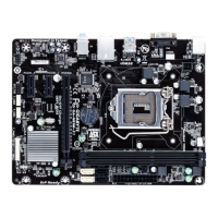
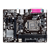
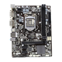
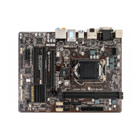
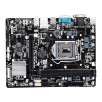
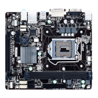
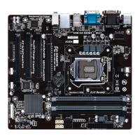
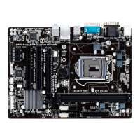
Diagram showing the physical arrangement of components on the motherboard.

Box Contents

Lists items included in the product package.

Motherboard Block Diagram

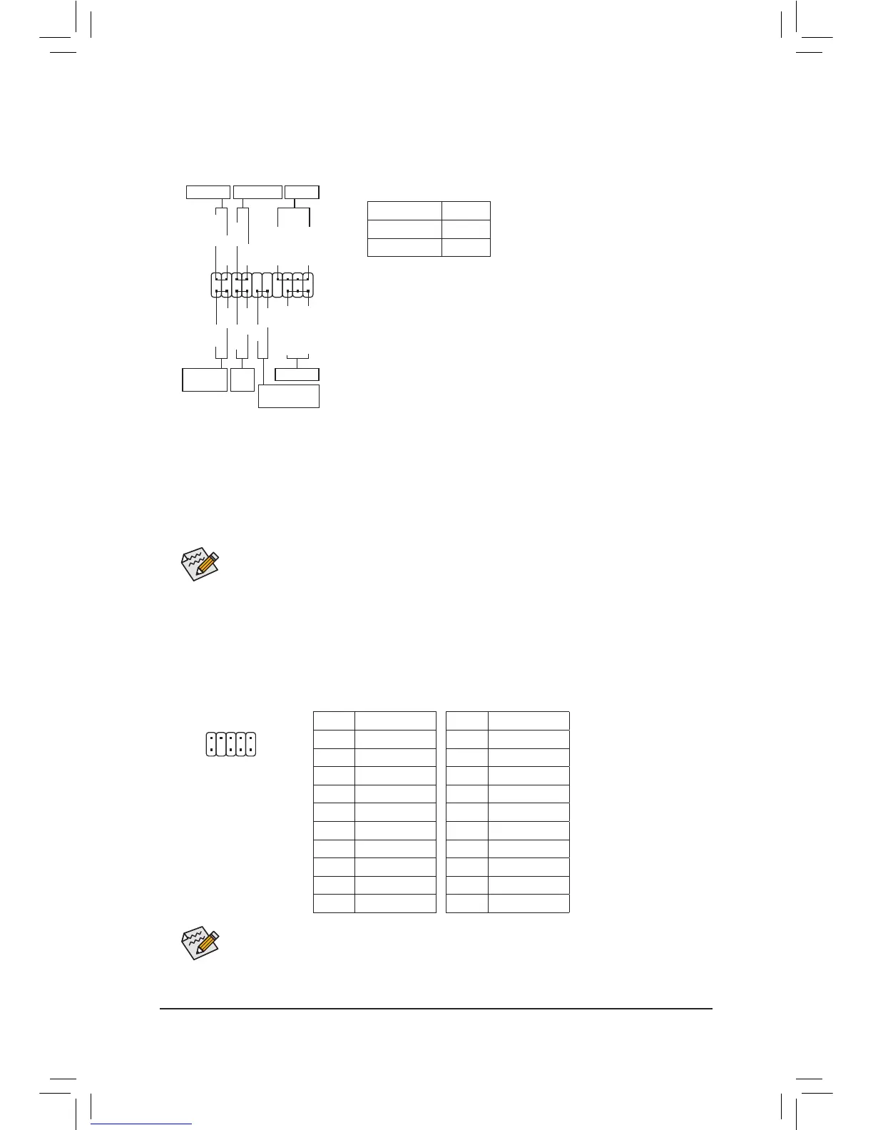
Diagram illustrating the internal architecture and data flow.

Chapter 1 Hardware Installation

Installation Precautions

Safety and general guidelines before installing hardware.

Product Specifications

Detailed technical specifications of the motherboard.

Installing the CPU

Step-by-step guide for CPU installation.

Installing the Memory

Step-by-step guide for memory installation.

Installing an Expansion Card

Instructions for installing expansion cards.

Back Panel Connectors

Description of I/O ports on the motherboard.

Internal Connectors

Explanation of internal headers and their pinouts.

Chapter 2 BIOS Setup

Startup Screen

Description of the initial BIOS screen and navigation.

M.I.T. (Memory Intelligent Tweaker)

Section for memory and system tuning.

System Information

Displays BIOS version, date, and system settings.

BIOS Features

Configuration options for system boot and features.

Peripherals

Settings for onboard devices like audio, LAN, USB.

Power Management

Configuration for system power states and wake-up events.

Save & Exit

Options for saving BIOS settings and exiting.

Chapter 3 Appendix

Drivers Installation

Instructions for installing motherboard drivers.

Regulatory Statements

Regulatory Notices

Legal statements regarding the manual's content and accuracy.

Environmental Compliance and Directives

Information on environmental directives (RoHS, WEEE) and recycling.

Contact Us

GIGABYTE Global Service System

Information on accessing GIGABYTE's online support portal.

Related product manuals