- 15 -
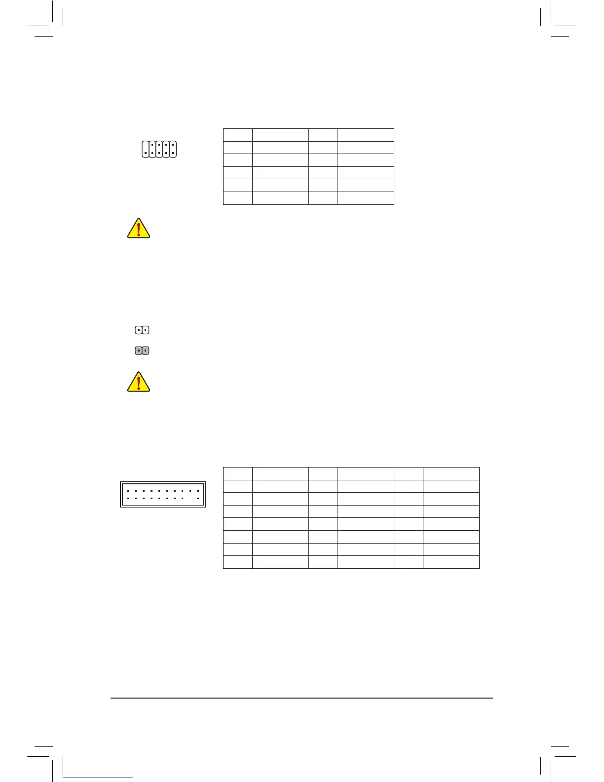
10) F_USB1/F_USB2 (USB 2.0/1.1 Headers)
The headers conform to USB 2.0/1.1 specication. Each USB header can provide two USB ports via an
optional USB bracket. For purchasing the optional USB bracket, please contact the local dealer.
11) CLR_CMOS (Clear CMOS Jumper)
Use this jumper to clear the BIOS conguration and reset the CMOS values to factory defaults. To clear
the CMOS values, use a metal object like a screwdriver to touch the two pins for a few seconds.
10
9
2
1
Pin No. Denition Pin No. Denition
1 Power (5V) 6 USB DY+
2 Power (5V) 7 GND
3 USB DX- 8 GND
4 USB DY- 9 No Pin
5 USB DX+ 10 NC
• Do not plug the IEEE 1394 bracket (2x5-pin) cable into the USB header.
• Prior to installing the USB bracket, be sure to turn off your computer and unplug the power cord from the power
outlet to prevent damage to the USB bracket.
• Always turn off your computer and unplug the power cord from the power outlet before clearing the CMOS values.
• After system restart, go to BIOS Setup to load factory defaults (select Load Optimized Defaults) or manually
congure the BIOS settings (refer to Chapter 2, "BIOS Setup," for BIOS congurations).
Open: Normal
Short: Clear CMOS Values
20
19
2
1
F_USB30
F_AUDIO(H)
DB_PORT
F_PANEL(NH) F_PANEL
(H61M-D2)
ACPI_CPT
(GA-IVB)
BIOS_PH
(GA-IVB)
SMB_CPT
(GA-IVB)
CLR_CMOS
CI
DIS_ME
GP15_CPT
(GA-IVB)
XDP_CPU
XDP_PCH
(GA-IVB)
TPM
w/housing
Voltage measurement module(X58A-OC)
PCIe power connector (SATA)(X58A-OC)
DIP
123
DIP
123
DIP
123
DIP
123
1
1
1
1
BIOS Switcher (X58A-OC)
PWM Switch (X58A-OC)
M_SATA
PWM Switch (SW1)(X79-UD7)
DIP
1 2 3 4 5
Voltage measurement points(G1.Sniper 3)
BIOS Switcher (SW4)
PCIe Control (Z87X-UP7)
ATX_12V_2X3
F_USB3 (Front Panel)
Pin No. Denition Pin No. Denition Pin No. Denition
1 LCLK 8 LAD2 15 SB3V
2 GND 9 VCC3 16 SERIRQ
3 LFRAME 10 LAD1 17 GND
4 No Pin 11 LAD0 18 NC
5 LRESET 12 GND 19 NC
6 NC 13 NC 20 SUSCLK
7 LAD3 14 ID
12) TPM (Trusted Platform Module Header)
You may connect a TPM (Trusted Platform Module) to this header.
 Loading...