- 27 - Hardware Installation
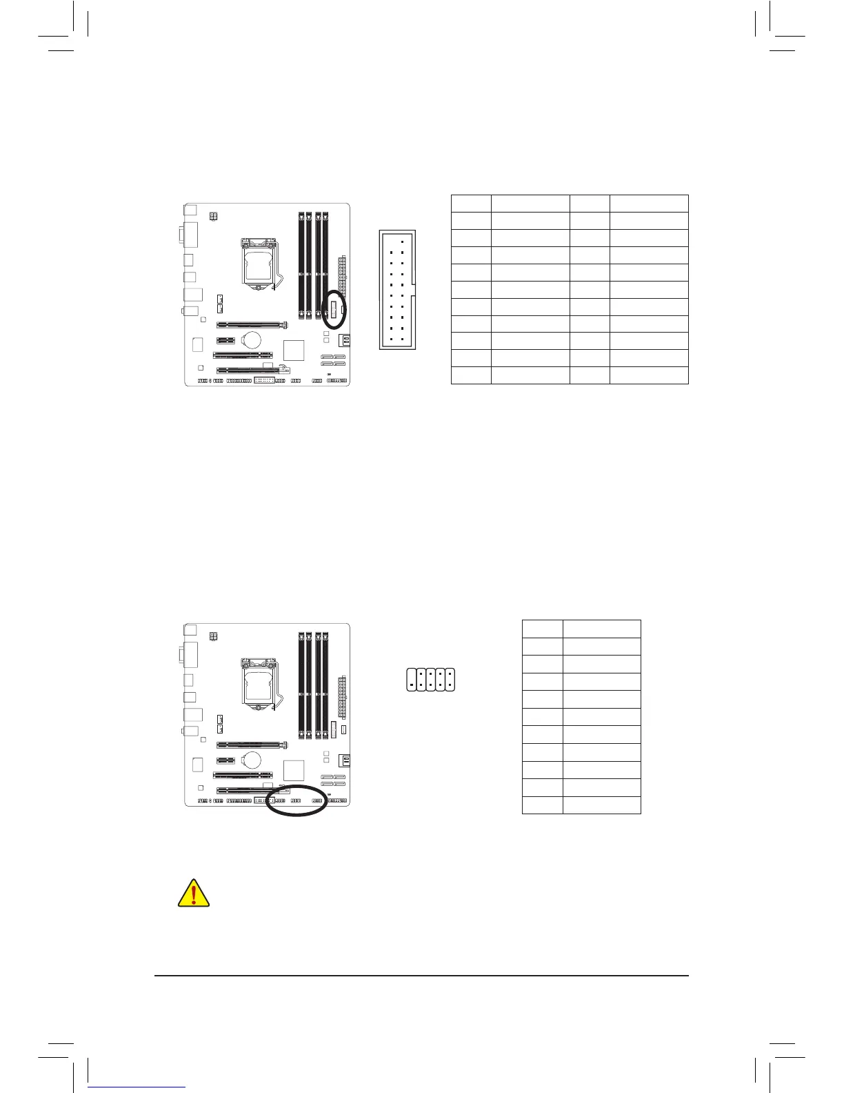
12) F_USB1/2/3 (USB 2.0/1.1 Headers)
The headers conform to USB 2.0/1.1 specication. Each USB header can provide two USB ports via an
optional USB bracket. For purchasing the optional USB bracket, please contact the local dealer.
Pin No. Denition
1 Power (5V)
2 Power (5V)
3 USB DX-
4 USB DY-
5 USB DX+
6 USB DY+
7 GND
8 GND
9 No Pin
10 NC
Do not plug the IEEE 1394 bracket (2x5-pin) cable into the USB 2.0/1.1 header. •
Prior to installing the USB bracket, be sure to turn off your computer and unplug the power cord •
from the power outlet to prevent damage to the USB bracket.
10
9
2
1
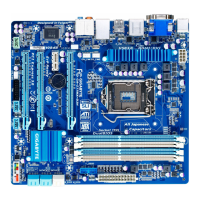
Pin No. Denition Pin No. Denition
1 VBUS 11 D2+
2 SSRX1- 12 D2-
3 SSRX1+ 13 GND
4 GND 14 SSTX2+
5 SSTX1- 15 SSTX2-
6
SSTX1+ 16
GND
7 GND 17 SSRX2+
8 D1- 18 SSRX2-
9 D1+ 19 VBUS
10
NC 20 No Pin
11) F_USB30 (USB 3.0/2.0 Header)
The header conforms to USB 3.0/2.0 specication and can provide two USB ports. For purchasing the
optional 3.5" front panel that provides two USB 3.0/2.0 ports, please contact the local dealer.
F_USB30
F_AUDIO(H)
DB_PORT
F_PANEL(NH) F_PANEL
(H61M-D2)
ACPI_CPT
(GA-IVB)
BIOS_PH
(GA-IVB)
SMB_CPT
(GA-IVB)
CLR_CMOS
CI
DIS_ME
GP15_CPT
(GA-IVB)
XDP_CPU
XDP_PCH
(GA-IVB)
TPM
w/housing
Voltage measurement module(X58A-OC)
PCIe power connector (SATA)(X58A-OC)
DIP
1 2 3
DIP
1 2 3
DIP
1 2 3
DIP
123
1
1
1
1
BIOS Switcher (X58A-OC)
PWM Switch (X58A-OC)
M_SATA
PWM Switch (SW1)(X79-UD7)
DIP
1 2 3 4 5
 Loading...