17
221469B
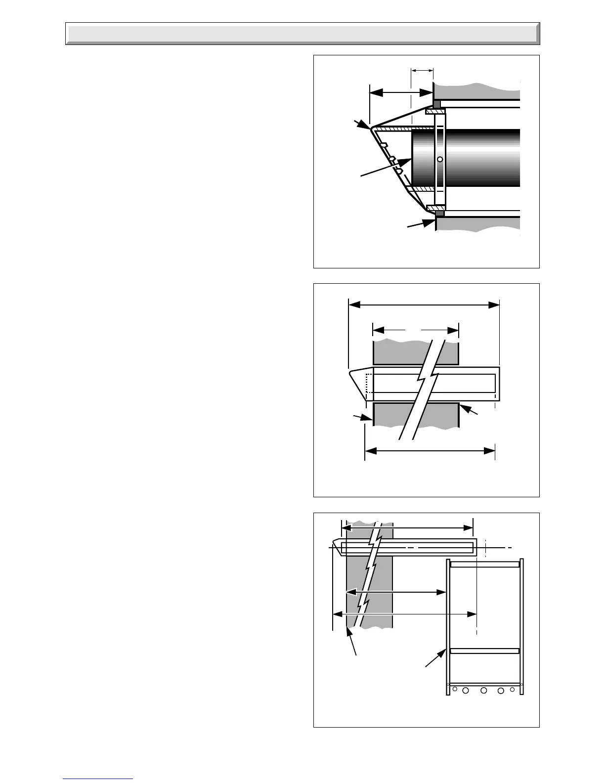
7 Flue Preparation
Diagram 7.1
Diagram 7.2
X + 125
( FLUE DUCT )
X
BOILER
MOUNTING
WALL
OUTSIDE
WALL
FACE
( AIR DUCT ASSEMBLY)
X + 173
Diagram 7.3
Y
Y + 229
(AIR DUCT
ASSEMBLY)
OUTSIDE
WALL
FACE
2301
(FLUE DUCT)
SIDE
OF
BOILER
MOUNTING
FRAME
Y + 181
SIDE FLUE DUCTS
STANDARD OR LONG
FLUE TERMINAL
REAR DUCT
STANDARD - LONG
2335
2333
FLUE
TERMINAL
FLUE
DUCT
OUTSIDE
WALL
FACE
22
63
7.1 Flue Length
For a rear flue, measure the distance from the outside wall face
to the boiler mounting wall. Check that the flue length will be
suitable, see diagram 3.1 for a standard flue system or diagram
3.3 for a 1, 2 or 3metre flue system.
For a side flue, measure the distance from the outside wall face
to the side of the boiler mounting frame. Check that the flue
length will be suitable, see diagram 3.2 for a standard flue
system or diagram 3.4 for a 1, 2 or 3metre flue system.
All flue systems are installed in a similar manner to the standard
flue.
Note: For all 1, 2 or 3metre flues make sure that the flue duct
is cut at the opposite end to the fixed spacer.
7.2 Rear Flue
Mark the air duct assembly and the flue duct at the lengths
shown in diagram 7.1 and 7.2, then cut to length, cutting square
and removing any burrs.
7.3 Side Flue
Mark the air duct assembly and the flue duct at the lengths
shown in diagram 7.1 and 7.3 then cut to length, cutting square
and removing any burrs.
 Loading...


