9
221469B
1 General Data
1.4 Requirements
The installation of this boiler must be carried out by a competent
person in accordance with the rules in force in the countries of
destination.
Manufacturer’s instructions, supplied.
Manufacturer’s instructions must not be taken as overriding
statutory requirements.
1.5 Data Label
The data label is at the top right hand side of the
inner case.
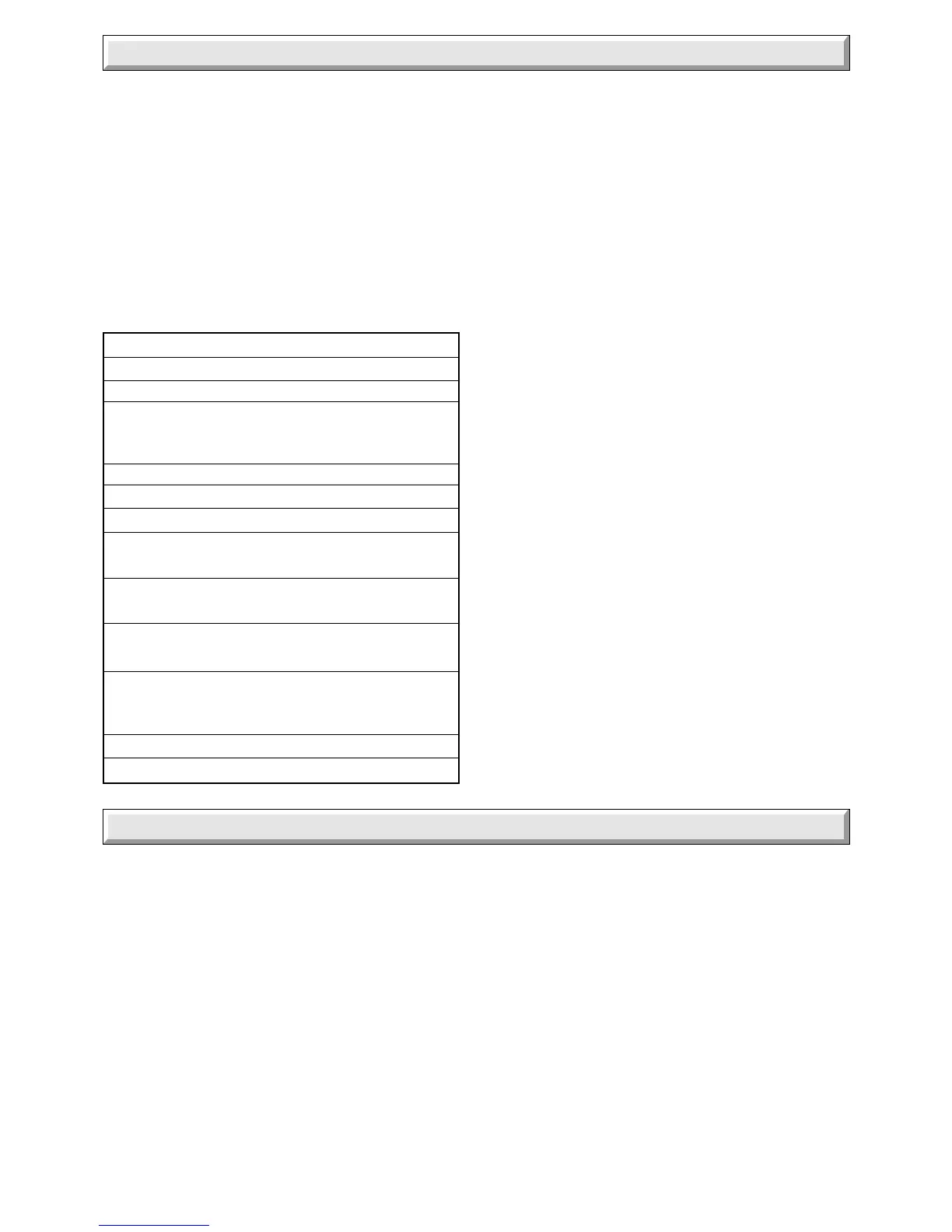
1.6 Data
Weight 47.2kg (104lb)
Gas connection Rc
1
/
2
(
1
/
2
in BSP)
Heating Flow and Return 22mm compression
D.H.W Inlet and Outlet
15mm compression (Ball valves are incorporated in water and
gas connections plus a drain point on all water connections).
Safety Valve preset 3bar (43.5lbf/in
2
)
Safety Valve Discharge 15mm compression
Water Content 1.74Litre (0.38gall)
Expansion Vessel 8Litre
Capacity (1.76gal)
Heating Cold Fill
Pressure 0.7bar (10.1lbf/in
2
) minimum
D.H.W Working
Pressure 0.5 to 10bar (7.25 to 188lbf/in
2
)
Maximum Heating System 119Litre (26.2gall)
Water Content (Larger systems will require
an additional expansion
vessel, refer to Section 4).
Electrical Supply 240V~50Hz
Electrical Rating 150W, fused 3A
1.7 Gas Supply
The gas installation shall be in accordance with the rules in force
in the countries of destination.
The supply from the governed meter must be of adequate size
to provide a steady inlet working pressure of 20mbar (8in wg) at
the boiler.
1.8 Electrical Supply
WARNING. This boiler must be earthed.
All system components shall be of an approved type.
The installation shall be in accordance with the rules in force in
the countries of destination.
Connection of the whole electrical system of the boiler and any
heating system controls to the electrical supply, must be through
one common isolator.
Isolation should be by a double pole switched fused spur box,
having a minimum contact separation of 3mm in each pole. The
fused spur box should be readily accessible and preferably
adjacent to the appliance. It should be identified as to its use.
Alternatively, a fused 3A 3pin plug and unswitched socket may
be used, provided they are not used in a room containing a bath
or shower.
The mains supply cable and other cables connected to the
boiler must be the PVC flexible type of at least 0.75mm
2
(24/
0.20mm).
2 Boiler Position
2.1 Location
This boiler must be installed in accordance with the rules in
force in the countries of destination.
This boiler is not suitable for fitting outside.
Any electrical switch must be positioned so that it cannot be
touched by a person using the bath or shower.
The boiler must be mounted on a flat wall which is sufficiently
robust to take its weight, refer to Section 1, “Data”.
If the location of the boiler or any part of the system is subject
to severe cold weather conditions, it is recommended that a
frost thermostat is fitted. Any part of the system that may be
vulnerable to freezing must be protected.
If the boiler is to be fitted into a cupboard, compartment or
unusual location, special procedures are necessary.
Make sure that the cupboard or compartment air vents are
positioned to be clear of obstructions at all times, refer to
Section 3, Cupboard/Compartment Ventilation.
2.2 Clearances
The boiler should be positioned so that at least the minimum
operational and servicing clearances are provided, see diagram
5 Instructions for Use. Additional clearances may be required
around the boiler for installation.
 Loading...


