19
221469B
Diagram 8.1
8 Gas and Water Connections
Diagram 8.2
WATER CONNECTIONS
UPWARD ROUTING
OF PIPEWORK
2298
'NOTCH' MARKING POSITION OF
SAFETY VALVE DISCHARGE
BOILER
MOUNTING
FRAME
2297
DOMESTIC
COLD
WATER
SUPPLY IN
CENTRAL
HEATING
FLOW
GAS
SERVICE
COCK
CENTRAL
HEATING
RETURN
DOMESTIC
HOT
WATER
OUT
63
SLOT (CLOSED)
SLOT
(CLOSED)
DRAIN POINT
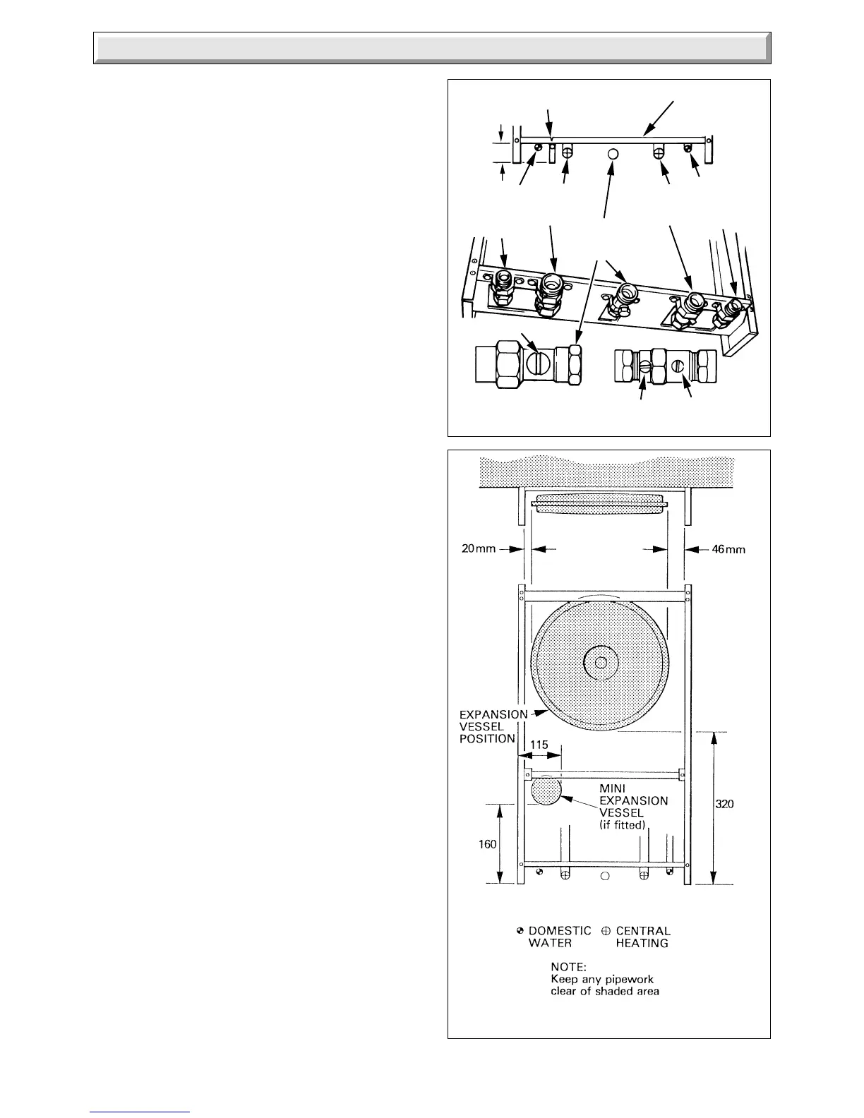
8.1 Gas Connection
Provision is made for the gas supply to be connected from
below or through the wall at the rear of the boiler, see diagram
8.1 for position.
Refer also to “Gas Supply”, Section 1.8.
Make the gas supply connection to the gas service cock.
Slacken or remove the clip, as preferred, while making the
connection. Do not subject the gas service cock to heat as you
may damage the seals.
8.2 Water Connections
Provision is made for the domestic cold water inlet to be
connected from below or through an internal wall at the rear of
the boiler, see diagram 8.1 for position. Refer also to Section 5
“Domestic Hot Water System”.
Provision is made for the domestic hot outlet, heating flow and
return to be connected from below, through an internal wall at
the rear of the boiler or from above, passing down either side of
the boiler, see diagram 8.2 for clearances. Take care that any
pipework connected from above, within the boiler mounting
frame will clear the expansion vessels.
If necessary, temporarily fit the boiler, refer to Section 10.1,
“Mounting the Boiler”.
Flush out the domestic water and heating system before
connecting the boiler.
Make the connections to the domestic hot water outlet by
straight connector, and the heating system by means of the
isolating valves, see diagram 8.1.
Slacken or remove the clips, as preferred, while making the
connections. Do not subject any of the isolating valves to heat
as you may damage the seals.
Make sure that the drain points on the isolating valves are
positioned towards the front of the boiler, also that the drain and
operating screw heads are accessible.
8.3 Safety Valve Discharge
WARNING. It must not discharge above an entrance or window
or any type of public access area.
A short discharge pipe is supplied loose with the boiler, which
when fitted to the safety valve, will end below the boiler at the
mark between the cold water inlet and the heating flow, for
position and dimension see diagram 8.1.
This must be extended, using not less than 15mm od pipe, to
discharge, in a visible position, outside the building, facing
downwards, preferably over a drain. The pipe must have a
continuous fall and be routed to a position so that any discharge
of water, possibly boiling, or steam cannot create any danger to
persons, damage to property or external electrical components
and wiring.
Note. To ease future servicing it is advisable to use a compression
type fitting to extend the discharge pipe.
 Loading...


