29
221469B
This boiler will be fitted with either a Honeywell or SIT gas
control valve. It can be identified as shown:-
1.1 Servicing or Replacing Parts
To ensure the continued efficient and safe operation of the
appliance it is recommended that it is checked and serviced as
necessary at regular intervals.
The frequency of the servicing will depend upon the particular
installation conditions and usage, but in general once a year
should be enough.
The servicing of this boiler must be carried out by a competent
person in accordance with the rules in force in the countries of
destination.
Unless stated otherwise all parts removed for servicing or
replacing are fitted in the reverse order to removal.
After completing any servicing or renewing of any gas carrying
part, ALWAYS test for gas soundness and carry out functional
checks of controls.
Throw away all used sealing washers, gaskets and “O” rings
when renewing parts. Use the new ones supplied with the
spares assemblies.
1.2 Data Label
The data label is positioned on the inner case and can be seen
when the outer case is removed.
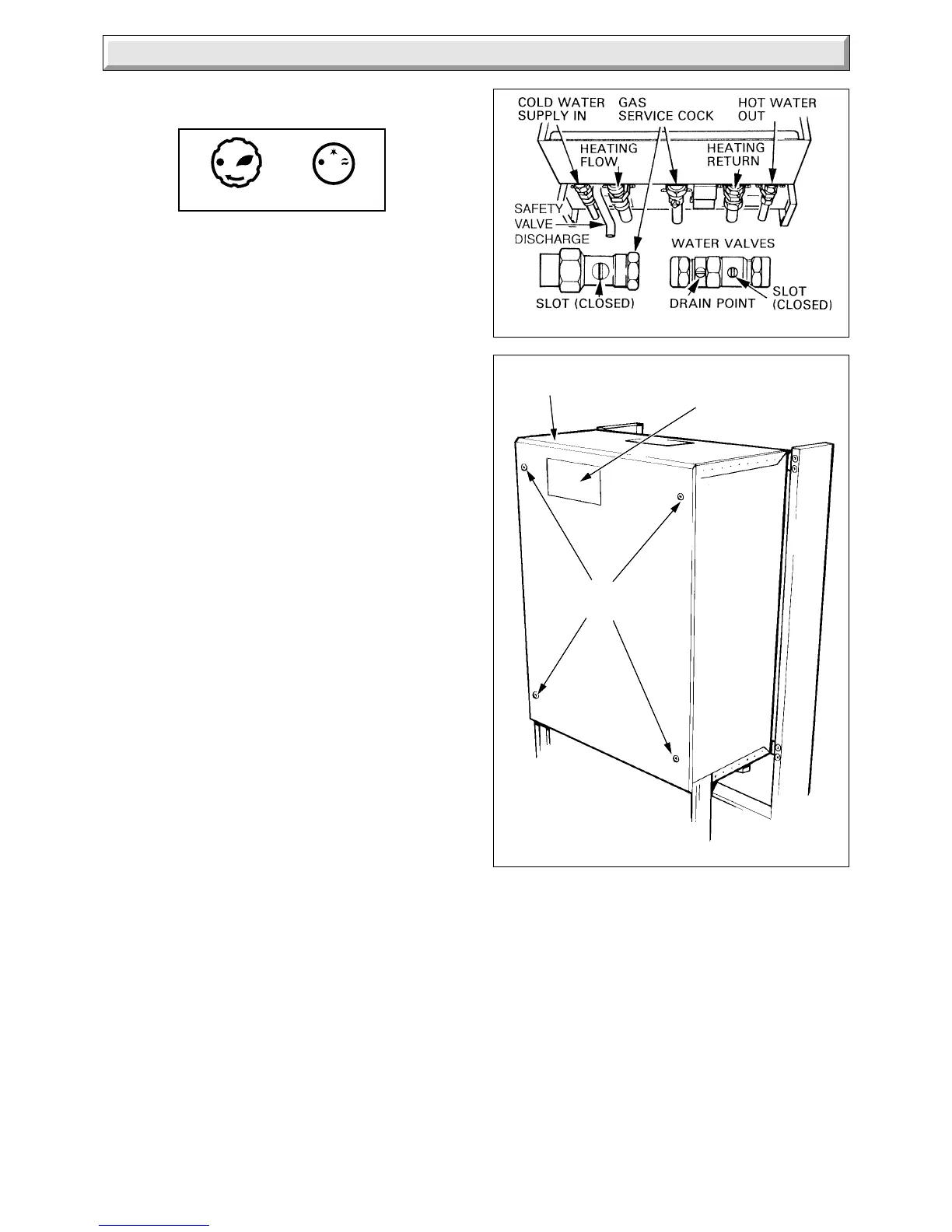
1.3 Isolation of Boiler
Before starting any servicing or the replacement of parts, isolate
the boiler from the electrical supply at the external isolator and
close the gas service cock, see diagram 1.1.
Before disconnecting any water containing part, close the
appropriate isolating valves and release the water pressure
before draining the boiler, see diagram 1.1 and refer to Section
1.6 System Pressure.
1.4 Outer Case Removal
The door opens to the left or right hand side.
The door catch is spring loaded, to open, push the side opposite
to the hinge, then pull.
Remove the two screws securing the outer case then unhook
the case at the top and pull it forwards and off, see diagram 6.1
installation section.
Note: Remove the four securing screws if there is a clock/timer
fitted.
1.5 Cover - Inner Case
Remove the cover of the inner case, secured by four screws,
see diagram 1.2.
1.6 System Pressure and Draining
All water containing parts of the central heating circuit within the
boiler are under the system pressure. Before any parts of this
circuit are disconnected, isolate the central heating valves and
release the pressure by operating the pressure relief safety
valve, see diagram 11.2 installation section.
HONEYWELL
SIT
GAS AND WATER ISOLATING
Diagram 1.1
2793
Diagram 1.2
2797 S
SECURING
SCREWS
INNER CASE
COVER
DATA
LABEL
To gain access to the safety valve knob, remove the outer case,
refer to Section 1.4. Turn the knob in the direction of the arrow.
Drain the boiler heating circuit at the drain points on the
appropriate isolation valves, see diagram 1.1. Make sure that
the automatic air vent is working. Remove the cover of the inner
case, for access, refer to Section 1.5.
All water containing parts of the domestic hot water circuit of the
boiler will be under the supply water pressure. Before any parts
of this circuit are disconnected, isolate the domestic water
valves, open the hot water taps and drain the boiler at the
isolation valves, see diagram 1.1.
After replacing any water containing part of the central heating
system, make up the water loss, vent all air and pressurise the
system, refer to Commissioning in the Installation Instructions.
Check for water soundness and that the safety valve seats
without leaking.
1 General Data
 Loading...


