[page 28] | gpelectric.com
AC WIRING CHECKS
•
Ensureallwiresaresecured.InRVapplicationsuseziptiesorothernon-conductivefastenerstopreventchang
or damage from movement and vibration.
• Ensure strain reliefs or grommets are in place to prevent damage to the wiring or conduit where it passes through
the walls/bulkheads or other openings.
• If using large diameter multi-core cable, add additional external non-conductive strain relief(s) to prevent damage
to the Inverter/Charger case.
• After checking all AC connections and ensuring all the terminal set screws are tightened securely, replace the AC
Cover Plate, 3 x Phillips set screws, and the covers on the main and sub panels.
AC WIRING FOR MARINE APPLICATIONS
To comply with American Boat and Yacht Council (ABYC) requirements for marine installations, all wire connections into the AC
terminal blocks must be protected with stainless steel wire protectors such as pin terminals to prevent wire damage from the
set screw.
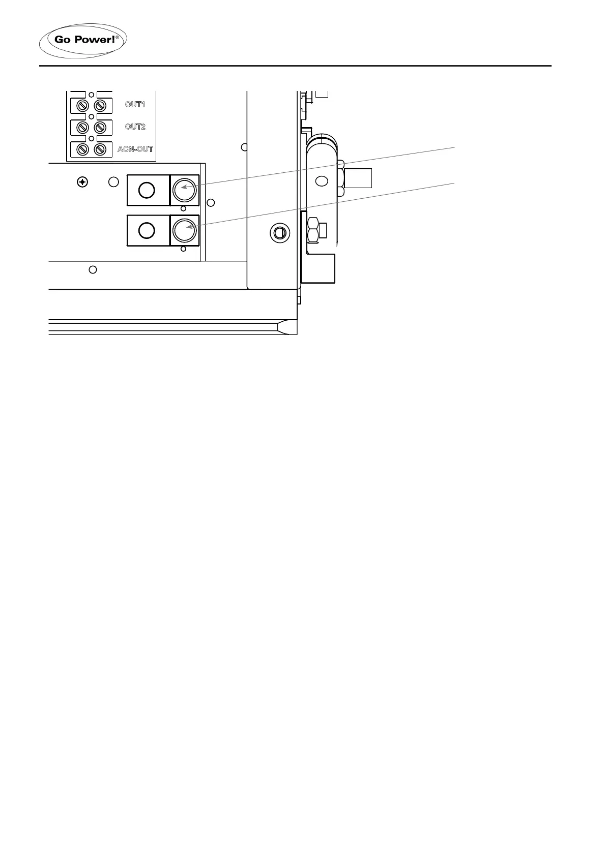
INSTALLATION
OUT1
OUT2
ACN-OUT
ACN-IN
IN1
IN2
OUT1
OUT2
ACN-OUT
ACN-IN
size : 55x36.5mm