gpelectric.com | [page 27]
•
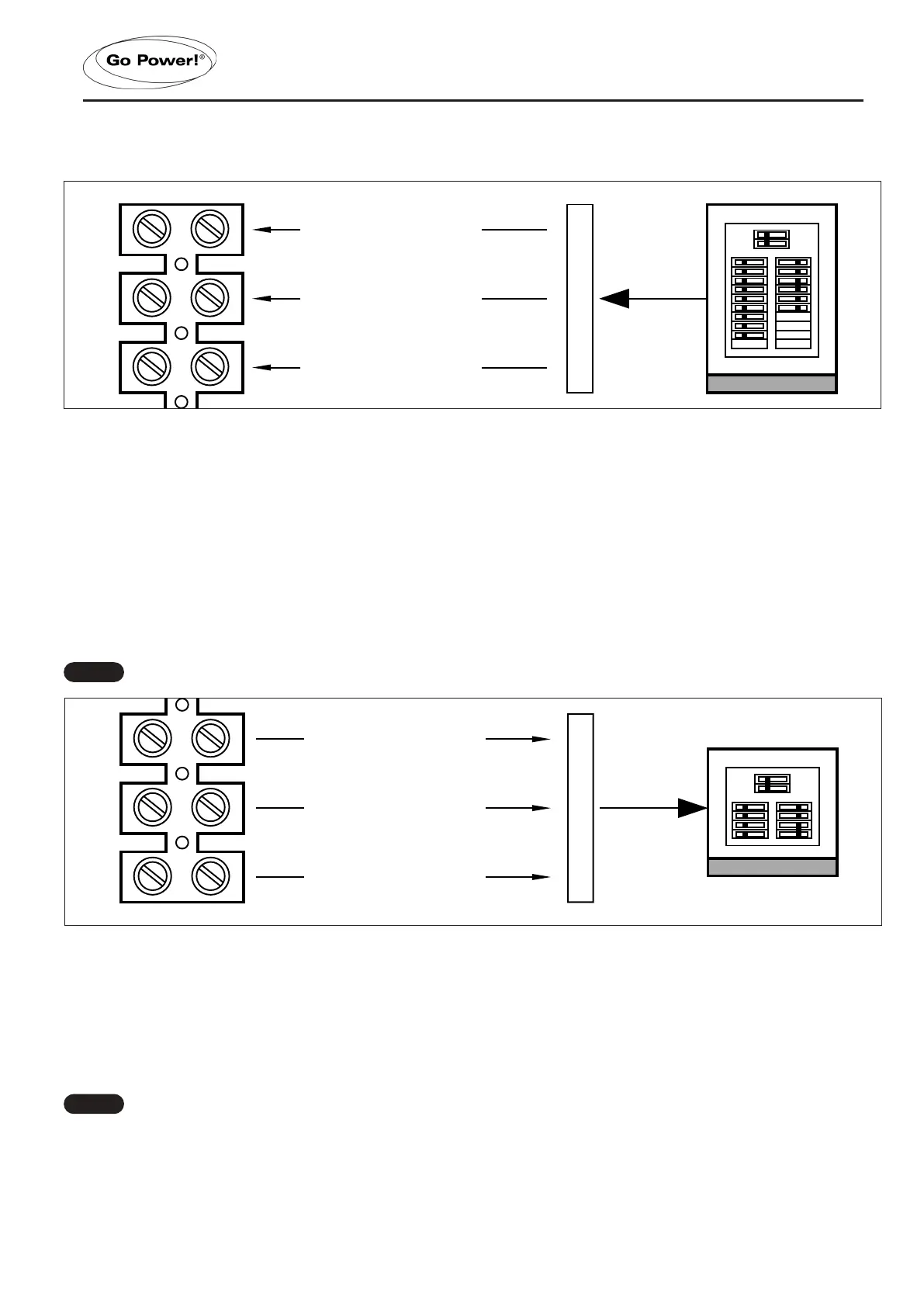
Connect the NEUTRAL (white) from the main panel to the Inverter/Chargers ACN-IN terminal. Tighten the terminal
securely to 16 in lbf (1.8 N-m).
AC OUTPUTS WIRING
•
Route the wires (hot, neutral, and ground) from the sub panel through the AC INV. Output strain relief clamp.
Tighten the strain relief clamp securely on the wires. Always leave a little extra slack in the wiring.
• Connect the OUT1 wire (black) and OUT2 (red) from the Inverter/Charger to the sub panel. Tighten the terminals
securely, to 16 in lbf (1.8 N-m).
•
Connect the ACN-OUT Neutral out (white) from the Inverter/Charger to the sub panel. Tighten the terminal securely,
to 16 in lbf (1.8 N-m).
• To prevent possible damage to the case, always add additional external non-conductive strain relief when using
large diameter multi-conductor cables for AC inputs and AC outputs
Double-check the manufacturer’s side of the terminal block. Tighten to 16 in lbf (1.8 N-m) if they come loose.
AC GROUND WIRING
•
Connect the ground (Green) wire from the main panel to the AC Ground IN terminal. Tighten the terminal securely,
to 16 in lbf (1.8 N-m)
•
Connect the ground (Green) wire from the sub panel to the AC Ground OUT terminal. Tighten the terminal securely,
to to 16 in lbf (1.8 N-m)
The Ground terminals are lugs and they are not labelled within the compartment. See diagram on the
following page.
INSTALLATION
IN 1
AC Live from main panel
IN 2
AC Live from main panel
ACN-IN
AC Neutral from main panel
OUT 1
AC Live to sub panel
OUT 2
AC Live to sub panel
ACN-OUT
AC Neutral to sub panel
IN 1
AC Live from main panel
IN 2
AC Live from main panel
ACN-IN
AC Neutral from main panel
OUT 1
AC Live to sub panel
OUT 2
AC Live to sub panel
ACN-OUT
AC Neutral to sub panel
Note
Note
 Loading...