5
Avoid dusty or smoky environments or locations near sources of heat.
For proper installation, use the template supplied with the product.
1. Position the top of the template at a height of 1.65m.
2. If you are going to use an embedding box to pass the wiring through, make sure that it is in line with the holes
corresponding to the box model chosen and fix the connector. If you prefer to fix the connector directly to the
wall, make four 6mm holes at the points indicated (A), insert the wall plugs supplied and screw in the connector.
3. Pass the installation wires through the middle hole and connect them to the removable terminals as shown in the
wiring diagrams. Before connecting the removable terminals to the monitor, configure the switch as indicated
below.
4. Connect the removable terminals to the monitor and place the monitor in front of the connector, making sure the
fixings line up. Move the monitor downwards to secure it.
INSTALLATION
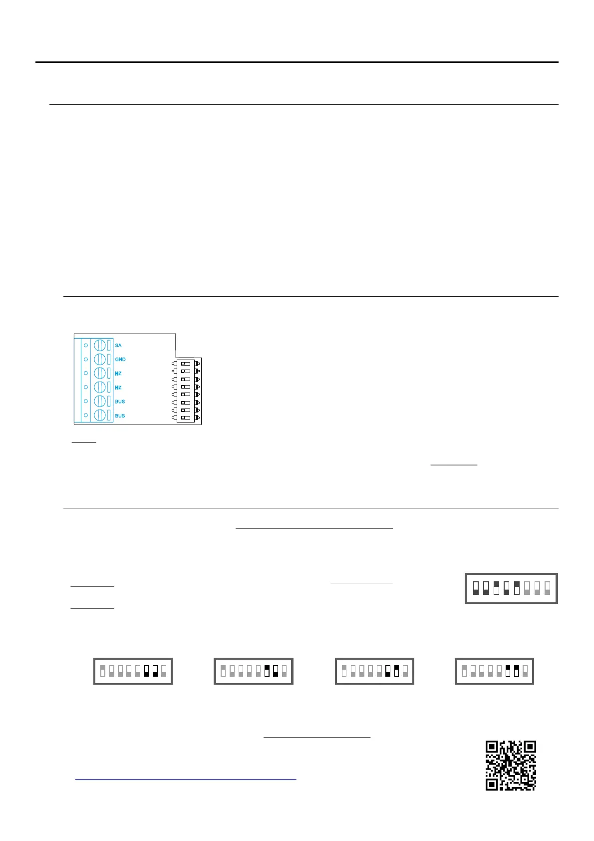
INSTALLATION TERMINALS (J)
For ease of installation, the installation terminals are removable and supplied in a separate bag. Once the
terminals are wired, place them in position.
Connect only on the master monitor. The signal received is then
transmitted to the slave monitors in the same apartment through the
BUS.
BUS, BUS: Communication BUS (non-polarised).
SA, GND: Auxiliary call repeater output (max 50mA/12V), relay
SAR-12/24.
HZ, HZ: Apartment front door button input:
CONFIGURATION SWITCHES (I)
SA
GND
HZ
HZ
ON
1 2 3 4 5 6 7
8
BUS
BUS
ART 4/G2+MONITOR
Switches 6 and 7: These define whether the monitor is master or slave. Each apartment must have one master
monitor, and only one.
Master Slave 1 Slave 2 Slave 3
Switch 8: This activates the end-of-line resistance in the ON position.Activate it in monitors where the bus cable ends.
Deactivate it only in intermediate monitors.
The switches set to OFF have a zero value. The values of the switches set to ON are shown in the table below. The
monitor code is the sum of the values of the switches set to ON.
Switches 1 to 5: Sets the monitor address (addresses to 3 ).1 2
Note: HZ push button function mode (ART 4/G2+ monitor "V.04 or later):" When HZ push button is pressed will be
call tone and activate the output of auxiliary call repeater with standby monitor call process m ation process, , com unic
( ), intercom .HZ tone with lower audio level process and "Do not disturb" mode Important: Up to 8 monitors/
apartments with push button "HZ" activated at the same time (with system and monitors in standby).
1 2 3
ON
4 5 6 7 8 1 2 3
ON
4 5 6 7 8 1 2 3
ON
4 5 6 7 8 1 2 3
ON
4 5 6 7 8
1 2 3
ON
Example: 0+ 0+4+0+16 = 20
Switch number: 1 2 3 4 5
Val ON:1 2 4 8 16ue when
Table of values
4 5 6 7 8
Important: Apartment 1 (Dip1 to ON & Dip2-Dip5 to OFF)
ART 4/G2+ monitor with V.03 and later.
Important: Apartment 32 (Dip1 - Dip5 to OFF)
*
Villa (Soul Door Panel)
*
MANUAL
TS5110 ART 4
Building / Villa (Nexa Door Panel)
If you have the “S5110 ART 4” villa kit with Soul door panel download 4, “TS5110 ART
(c d 5012212 )” QR o n web:o e 4 user manual from the next r i the link Golmar
h! ps://doc.golmar.es/search/manual/50122124
 Loading...