4
CODEPROX-N
www.golmar-seguridad.es
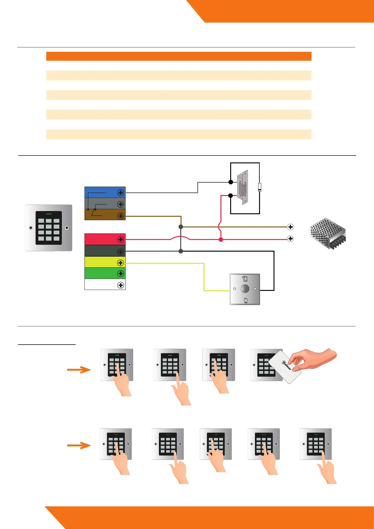
6.CONNECTION
7.STANDALONE CONNECTION DIAGRAM
WIRE COLOR FUNCTION DESCRIPTION
Red 12Vdc Input 12-18V DC current
Black GND GND
Blue NO Normally open relay output
Brown Common Common contact for relay output
Grey NC Normally closed relay output
Yel l ow Opening Exit pushbutton
Green D0 Wiegand Data 0 output
White D1 Wiegand Data 1 output
NC
COM
NO
OPEN
GND
D1
DO
Blue
Grey
Brown
Red
Yellow
Green
Black
+12V DC
White
+12V
GND
1N4004
1
2 3
4
5 6
7
8 9
*
0 #
IMPORTANT: Do not forget to connect the supplied diode (1N4004) in parallel to the lock release to protect the equipment.
8.BASIC PROGRAMMING
Basic programming (user registration/deletion):
8.1. USER REGISTRATION
1
2 3
4
5 6
7
8 9
*
0 #
Master code
1
2 3
4
5 6
7
8 9
*
0 #
#
1
2 3
4
5 6
7
8 9
*
0 #
1
1
2 3
4
5 6
7
8 9
*
0 #
Sistemas de comunicación S.A.
Approach card
to the reader
1
2 3
4
5 6
7
8 9
*
0 #
Master code
1
2 3
4
5 6
7
8 9
*
0 #
#
1
2 3
4
5 6
7
8 9
*
0 #
PIN
(ac�va�on code
1
2 3
4
5 6
7
8 9
*
0 #
#
1
2 3
4
5 6
7
8 9
*
0 #
1
CARD
REGISTRATION
PIN
REGISTRATION
 Loading...