24
05 Installation User Manual V1.4-2022-08-30
6 Electrical Connection
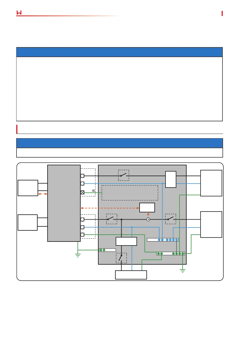
6.1 System Wiring Diagram
NOTICE
The following diagram is applicable to areas in Australia, New Zealand, South Africa, etc.
NOTICE
• N and PE wiring via ON-GRID and BACK-UP ports of the inverter are dierent based on the
regulation requirements of dierent regions. Refer to the specic requirements of local
regulations.
• There are integrated relays inside of the inverter’s ON-GRID and BACK-UP AC ports. When
the inverter is in the o-grid mode, the ON-GRID relay is disconnected; while when the
inverter is in grid-tied mode, it is connected.
• When the inverter is powered on, the BACK-UP AC port is live. Power o the inverter rst
if maintenance is required for the loads connected to BACK-UP ports. Otherwise, it may
cause electric shock.
N and PE cables are connected together in the Main Panel for wiring.
ON-GRID
BACK-UP
BAT
PV
Meter
E-N Link
N-BAR
E-BAR
E-BAR
or
L
N
PE
BMS
CT
L
L
N
N
PE
PE
L
N
PE
L
N
PE
BACK-UP
Loads
Smart
meter
Utility grid
Normal loads
Battery
PV string
RCD
RCD
Do not wire in this position
if N and PE cables are
connected together.
 Loading...