37
User Manual V1.4-2022-08-30 06 Electrical Connection
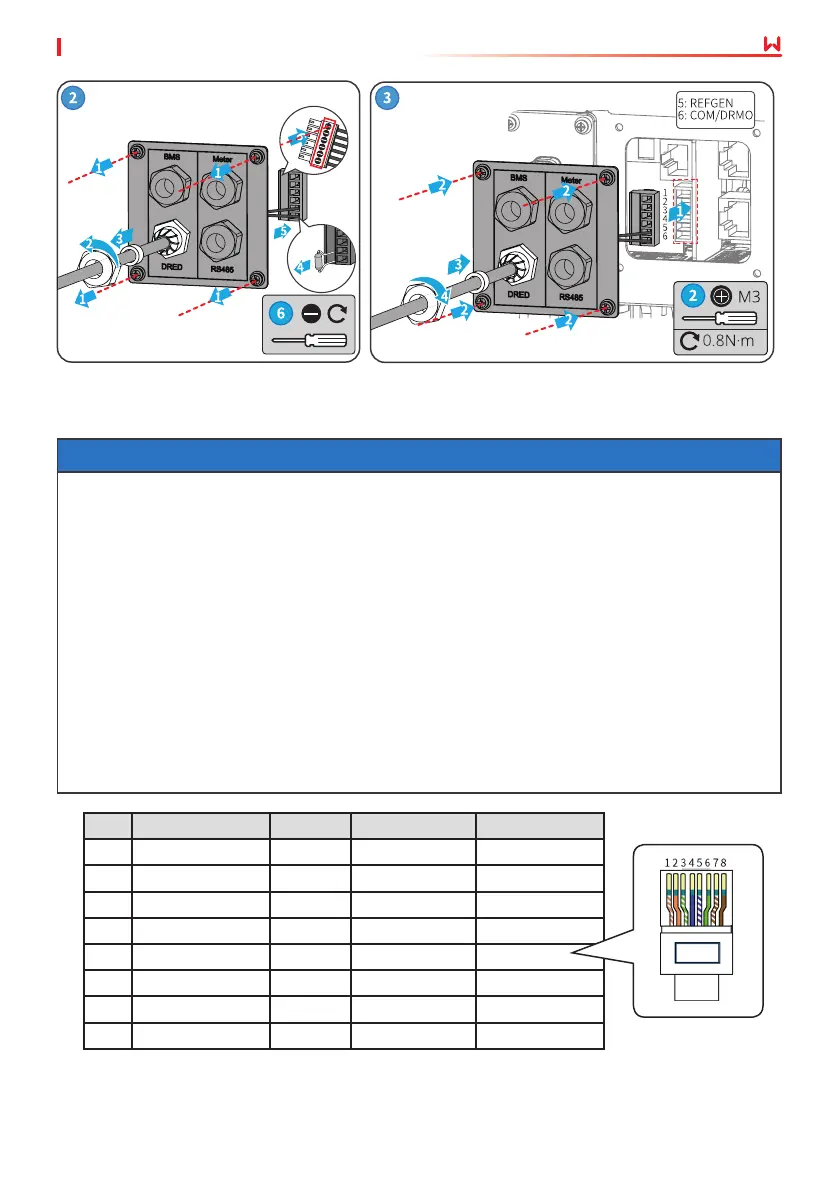
6.7.2 Connecting BMS or Meter Communication Cable (Optional)
NOTICE
• The smart meter and CT have been preset parameters before delivered with the inverter.
Do not modify the relevant parameters.
• The BMS communication cable and communication cable between the inverter and the
smart meter is included. For Battery-Ready inverters, the communication cable is not
included and should be prepared by customers.
• One smart meter can be connected to one inverter. Do not connect one smart meter
to multiple inverters. Contact the manufacturer or dealer to purchase additional smart
meter(s) if you need.
• Ensure that CT connects with the corresponding phase line: CT1 is connected to L1; CT2 is
connected to L2; and CT3 is connected to L3. And ensure that the CT is connected in the
right direction. Please refer to the smart meter user manual for detailed operations.
• RJ45 connector with the following denition can be connected for BMS and meter
communication:
No. Color BMS Smart meter RS485
1 Orange&White 485_A2 NC 485_A
2 Orange NC NC 485_B
3 Green&White 485_B2 485_B1 485_A
4 Blue CAN_H NC NC
5 Blue&White CAN_L NC NC
6 Green NC 485_A1 485_B
7 Brown&White NC 485_B1 NC
8 Brown NC 485_A1 NC
 Loading...