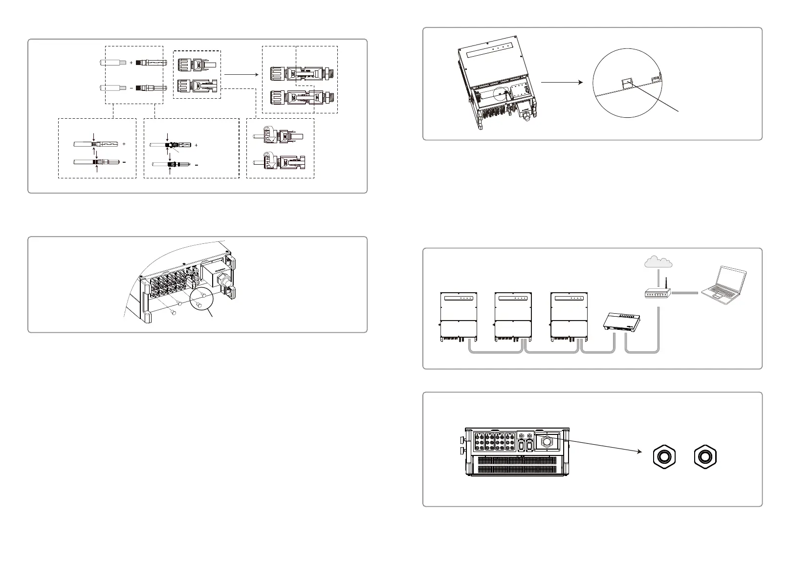
Inverter
RS485
EzLogger Pro
RS485RS485
PC
Router
Internet
Inverter
Inverter
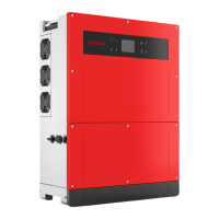
Please use special tools to do crimping
MC4 & QC4.10 DEVALAN & AMPHENOL
Do not crimp wire
into the limit buckle.
Negative connector
Positive connector
Inverter side
The installation method for DC connector.
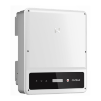
To better dustproof and waterproof the internal inverter, all DC connectors provided in the
accessory bag should be connected to the inverter. If only some of the DC connectors are used,
the DC connectors without connection should be blocked with a non-conductive insulator.
This function is only for local firmware upgrades and parameter calibrations.
4.4.2 RS485 Communication
This function only applies to the inverter with RS485 ports.
The RS485 port of the inverter is used to connect the EzLogger Pro, and the total length of
connecting cable should not exceed 1000m.
Communication lines must be separated from other power lines to prevent interference to the
communication. RS485 connections are shown as below.
Plug with PV waterproof plug
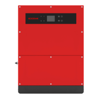
2. Insert the USB data cable
1. Open the bottom cover
4.3.5 DC Switch
The DC switch is designed to be safely disconnected from the DC input if required.
The inverter works automatically when the input and output meet the requirements. Rotating
the DC switch to the 'OFF' position will immediately cut off the flow of DC current.
Rotate the DC switch to the 'ON' position before starting the inverter.
4.4 Communication Connection
Inverter operation data can be transferred by USB, RS485 or WI-FI Module to a PC with monitoring
software or to a data logger device ( e.g Ezlogger Pro). USB is only used for service debugging; The
RS485 is the standard communication choice for the inverter, and WI-FI module can be used
optionally for communication.
4.4.1 USB Connection
USB cable must be connected according to the following steps, shown below:
The connection steps of RS485 communication of MT series are as follows:
Step 1: Find the RS485 terminal and screw out the screw cap.
RS485 RS485
15 16
 Loading...