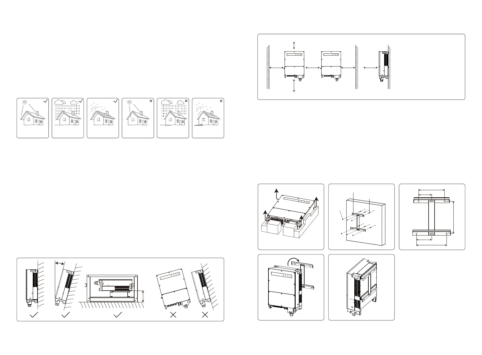
To ensure heat dissipation and convenient disassembly, the minimum clearance around the
inverter should not be less than the following values:
The upward part
The downward part
The front part
Both sides
Interval
------------ 200mm
-------- 500mm
---------------- 500mm
------------------- 1000mm
----------------------- 1200mm
500mm
1200mm1000mm 1000mm 500mm
200mm
Backboard Installation
Expansion Pipe
Nut
4.2.2 Transport And Mounting Precedure
1. Two operators are required when moving the inverter to hold the handle and arm-brace
respectively.
2. Use the wall-mounted bracket as a template and drill 6 holes on the wall: 13 mm diameter and
65 mm deep.
3. Fix the wall-mounted bracket on the wall with six expansion bolts from the accessory bag.
4. Carry the inverter with the handles on both sides of the inverter.
5. Place the inverter on the wall-mounted bracket as illustrated.
415
166.5
333
194
388
4.2 Equipment Installation
4.2.1 Select the Installation Location
1. Take the bearing capacity of the wall into account. The wall (e.g. concrete and metal) should
be strong enough to hold the weight of the inverter over a long period of time.
2. Install the unit where it is accessible to service or provide an electrical connection.
3. Do not install the unit on the wall containing or housing flammable materials.
4. Ensure the installation location is well ventilated.
5. Inverters should not be installed near flammable or explosive items. Any strong electro-mag-
netic forces should be kept away from the installation site.
6. Install the unit at eye level for convenient operation and maintenance.
7. Install the unit vertically or tilted backwards of no more than 15 ° , no lateral tilt is allowed.Wir-
ing area should face downwards. Horizontal installation requires more than 250mm elevation.
4 Installation
4.1 Mounting Instructions
1. To achieve optimal performance, the ambient temperature should be lower than 45℃.
2. For easy maintenance, we suggest installing the inverter at eye level.
3. Inverters should not be installed near flammable or explosive items. Strong electro-magnetic
forces should be kept away from installation site.
4. Product label and warning symbols should be placed at a location that is easy to see / read by
the users.
5. Ensure to install the inverter at a place where it is protected from direct sunlight, rain and snow.
Max
15°
Over
250mm
Accumulated snow
Keep away
from sunlight
Keep dry
Keep it clear
of snow
Sun Rain
09 10
 Loading...