Typical Installation, with circulation
10 309812D
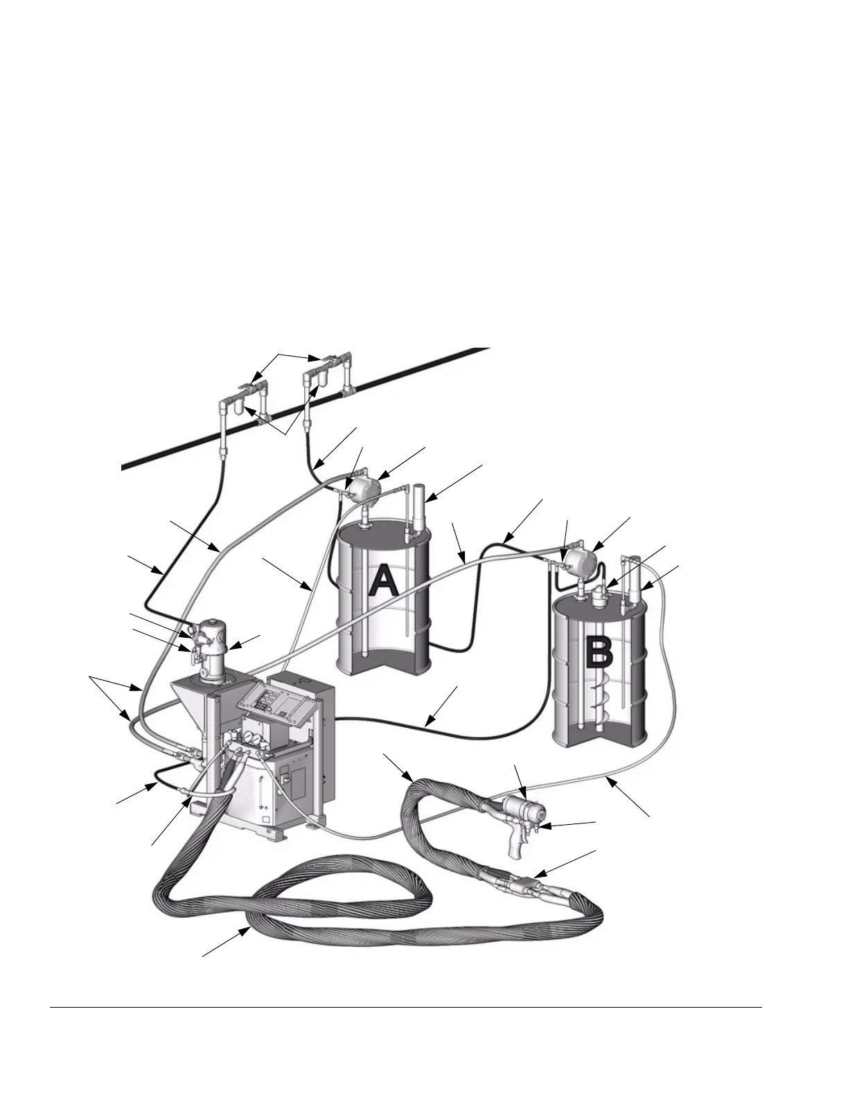
Typical Installation, with circulation
Key for FIG. 1
A Air Powered Reactor
B Heated Hose (see page 38)
C Fluid Temperature Sensor (FTS)
D Heated Whip Hose (see page 38)
E Fusion Spray Gun (see page 38)
F Gun Air Supply Hose
G Feed Pump Air Supply Lines
(part of Air Supply Kit, page 38)
J Fluid Supply Lines
K Feed Pumps (see page 38)
L Agitator
M Desiccant Dryer (part of Return Tube Kit, page 38)
P Gun Fluid Manifold (part of Fusion gun)
Q Air Quick-Disconnect (part of Circulation Kit, page 38)
R Air Purge Lines (part of Circulation Kit, page 38)
S Air Line Shutoff Valve
U Proportioner Air Supply Line
W Air Filter/Separator
AR Air Regulator (part of Reactor, page 12)
BV Bleed-Type Master Air Valve (part of Reactor, page 12)
FIG. 1: Typical Installation, with circulation (246037 Air Powered Reactor Shown)
A
B
C*
D
E
F
K
L
M
G
J
K
TI3675a
R
P
W
R
* Shown exposed for clarity. Wrap with tape during operation.
J
G
G
J
AR
BV
S
M
G
Q
Q
U

 Loading...