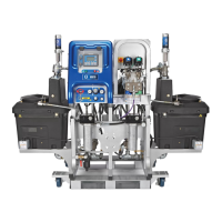
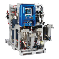
Component Identification
10 3A2776K
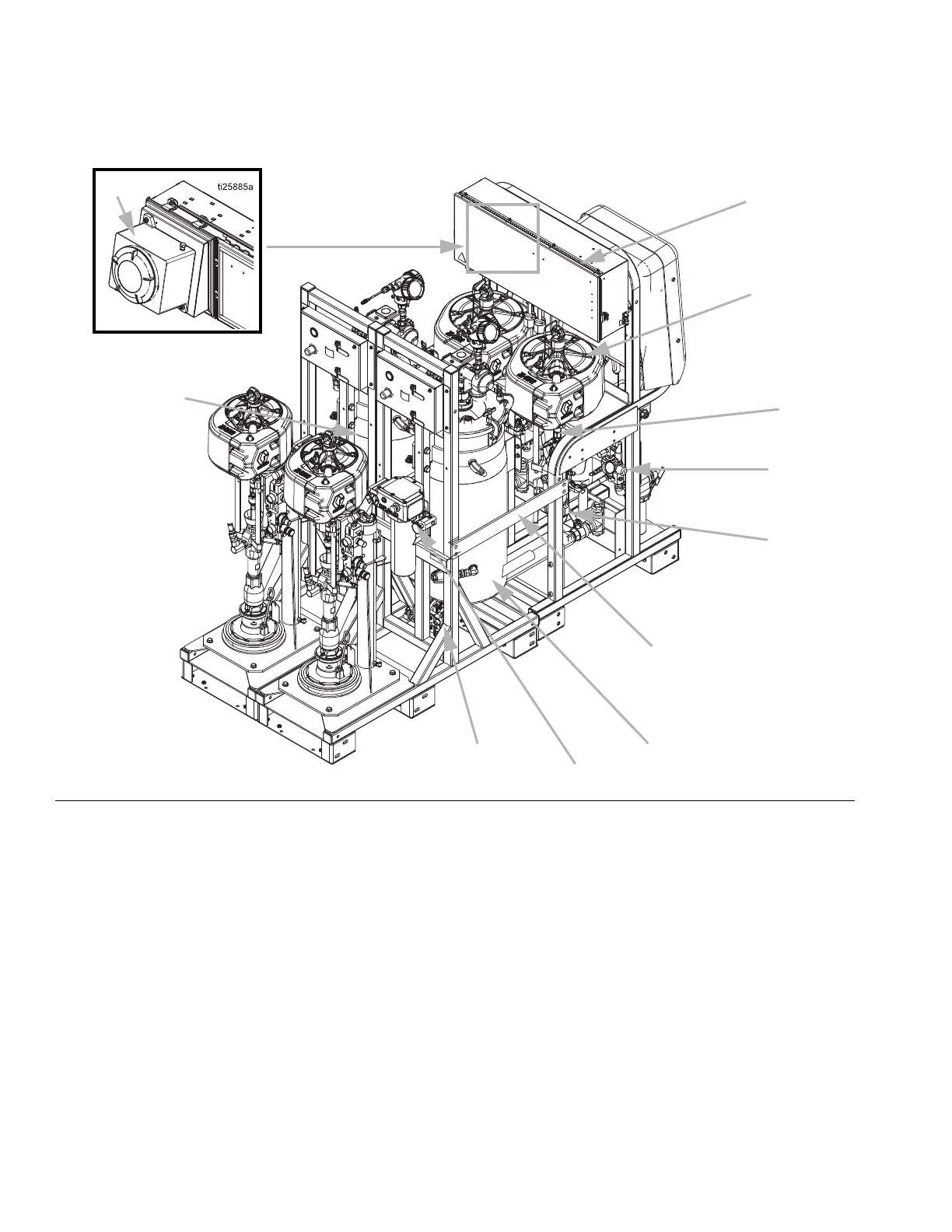
Typical Setup (Back View)
FIG. 2
U
Z
X (located between
metering pumps, not
visible in current view)
W
A1
B1
C1, A1
D1, A1
Hazardous Location
Models only
E1
A1
F1
Ref. Description
U Air Motor
W High Pressure Fluid Metering Pump
X Flush Pump (Merkur Pump)
Z Air Regulator for Feed Tanks and Pumps
A1 Heated Tank Circulation Components (uses a Viscon)
B1
TSL
™
Supply Bottle and Bracket
C1 Heated Fluid Circulation Pump for Hose Bundle
D1 Insulation Jacket
E1 Explosion Proof Box
(Hazardous Location System only)
F1 Junction Box Non-Hazardous Location System only)
or Purge Box (Hazardous Location System only)
Ref. Description
 Loading...