Component Identification
3A2776K 9
Component Identification
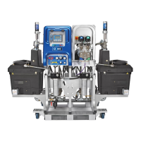
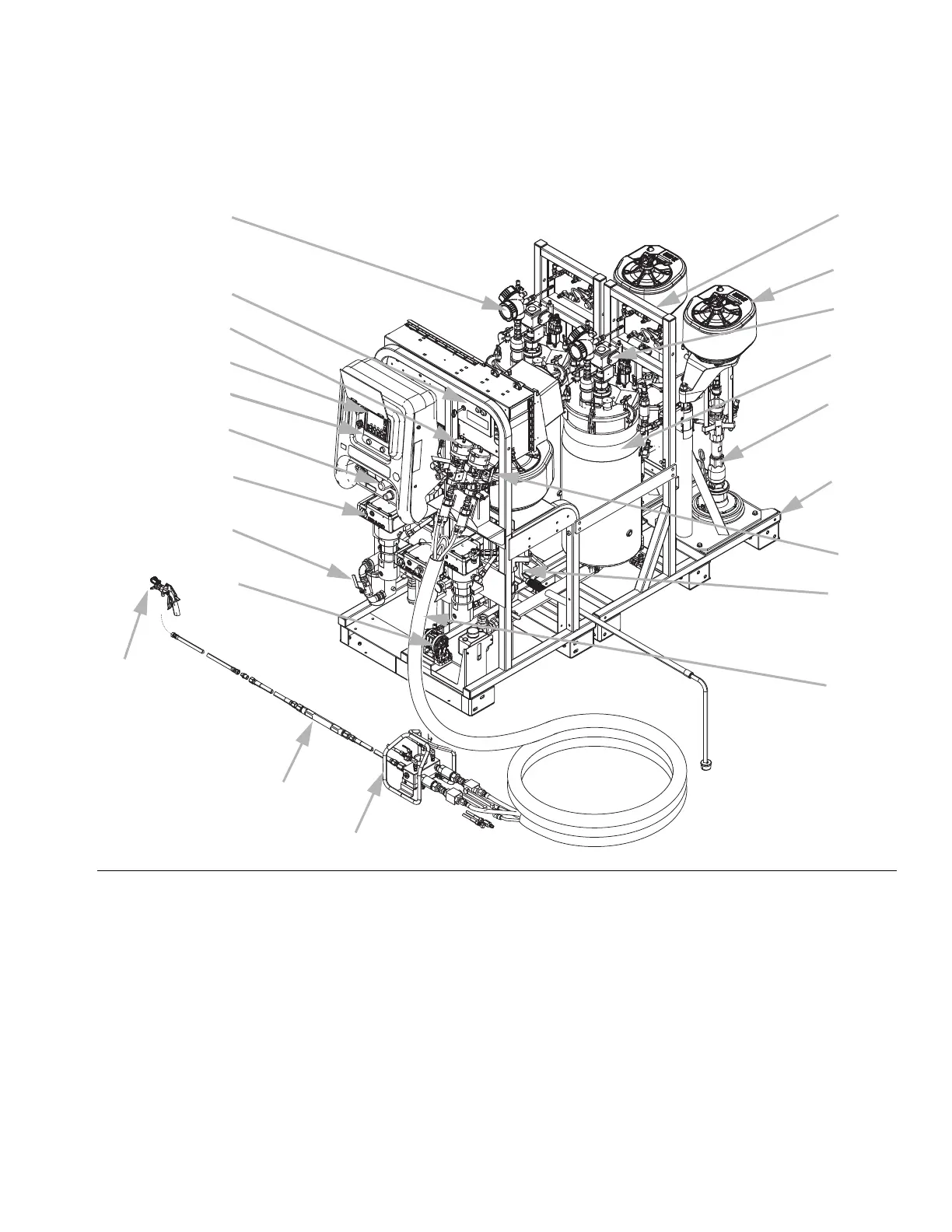
Typical Setup (Front View)
FIG. 1
A
B
C
D
G
H
J
L
M
N
P
R
S
T
U
V
Y
X
K
E, F
C1
Ref. Description
AFrame
B Fluid Control Assembly (see page 11)
C User Interface (see page 15)
D Metering Pumps Control On and Off Buttons
E Main Air Supply Shutoff Valve, 1 in. npt(f) Inlet
F Air Filter, 1-1/4 in.
G Air Controls for Sprayer and Flush Pump (see page 13)
H Viscon HP Heater for hose bundle
J Main Power and Heater Controls (see page 12)
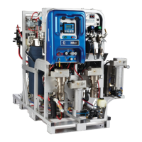
K Viscon HF Material Heater
L Air Powered Agitator with Lubricator
M Feed Pump
N Recirculation Control Valve
P Pressure Tank, Double-Wall Temperature Conditioned
R Remote Mix Manifold
S Static Mixer Assembly
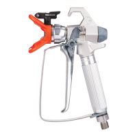
T Spray Gun
UAir Motor
V Feed Module Air Controls (see page 14)
X Flush Pump (Merkur Pump)
Y Radar Fluid Level Sensor
C1 Heated Fluid Circulation Pump for Hose Bundle
Ref. Description
 Loading...