Graham Corporation
10
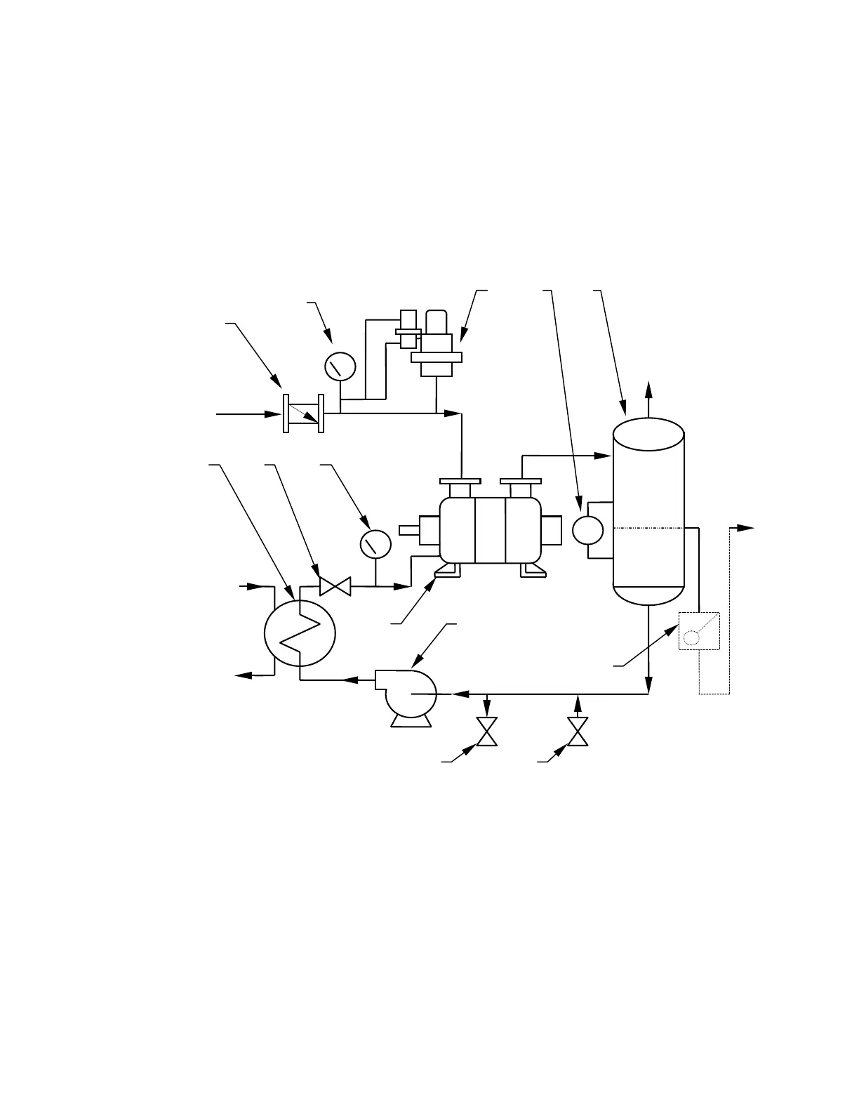
B) Typical Installation of Closed Loop with Total Recovery
This arrangement provides for the total recirculation of the service liquid. A heat exchanger is
added to the system to remove the heat of compression, friction, and condensation from the
service liquid before it is re-introduced to the pump.
The service liquid level in the separator of a total recovery system should be at or slightly
below the centerline of the pump shaft. A provision should be made for a high level overflow.
This will prevent starting the pump while it is full of liquid, which will damage the pump or
overload the motor.
A
E
B
D
L
J
M
K
Drain Make-up
Overflow
Cooling
Liquid
Cooling
Liquid Inlet
Process
Inlet
Gas
Outlet
G H
LG
C
F
A- Inlet Check Valve G- Shut-off or Throttling Valve
B- Pressure Gauge
(vacuum gauge for vacuum
service or compound gauge for compressor
service)
H-
J-
K-
Compound Gauge
Liquid Ring Pump
Recirculation Pump (recommended)
C-
D-
Vacuum Relief Valve
(not required for
compressor service)
Level Gauge
L-
Trap or Loop Seal
(required if dis-
charge pressure is above atmospheric
pressure)
E- Separator M- Drain Valve
F- Service Liquid Cooler N- Make-Up Valve
Closed Loop-Total Recovery
Diagram 2
 Loading...