Graham Corporation
A) Typical Installation of Once Through with No Recovery
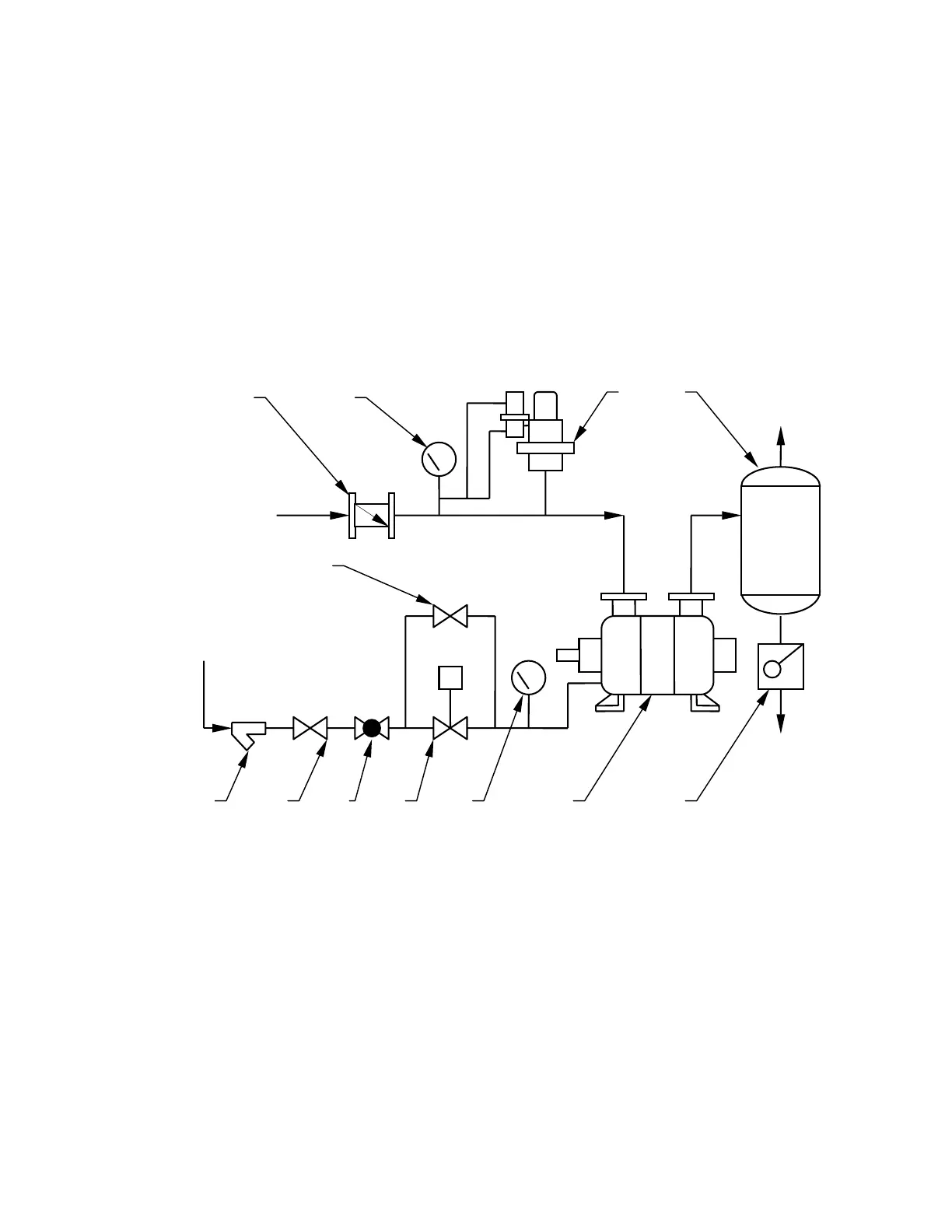
The service liquid is piped directly from a supply source to the pump. The liquid is separated
from the gas in the separator and discharged to a drain. No recirculation nor recovery takes
place. This is the most basic arrangement and can be used when service liquid conservation or
contamination is not a concern. A solenoid operated valve provides for flow of the liquid
simultaneously with the pump/motor operation. When the motor stops, the valve closes to
prevent the pump casing from filling with fluid. The by-pass valve is used to pre-fill the pump
at initial start-up only. It also can be used should the solenoid fail. When a manual valve is
used, it must be opened immediately after starting the motor and closed immediately before
turning the motor off.
Process
Inlet
Service
Liquid Inlet
Gas
Outlet
Liquid
Drain
S
A
D
F G H
E
J K
C
M
B
L
A- Inlet Check Valve G- Shut-off Valve
B- Pressure Gauge
(vacuum gauge for vacuum
service or compound gauge for compressor
service)
H-
J-
K-
Regulating Valve
Solenoid Valve
Compound Gauge
C-
D-
Vacuum Relief Valve
(not required for
compressor service)
Separator
L-
M-
Liquid Ring Pump
Trap
(required if discharge pressure
is above atmospheric pressure)
E- By-Pass Valve
F- Strainer
Once Through with No Recovery
Diagram 1
9
 Loading...