D Series Modular Air-cooled Scroll Chillers
31
6 Electric Control Cabinet
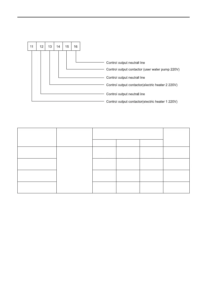
6.1 Wiring for Output Control Lines
Note:
The output control lines of the auxiliary electric heater 1, auxiliary electric heater 2 and the water pump
AC contactor are allowed to the terminal boards 11/12/13/14/15/16 of any module.
6.2 Specication of Power Cord and Air Switch
Model Power Supply
Min. sectional area of
the power cable (mm
2
)
Capability of
the Air Switch
(A)
Live Line Neutral Line Earth Line
LSQWRF65M/D-M
LSQWRF65M/NaD-M
380-415V 3N 50Hz
16 16 16 63
LSQWRF80M/D-M
LSQWRF80M/NaD-M
25 16 16 80
LSQWRF130M/D-M
LSQWRF130M/NaD-M
50 25 25 125
LSQWRF160M/D-M
LSQWRF160M/NaD-M
70 35 35 160
Notes:
(a) The specications of the breaker and power cable listed in the table above are determined based on
the maximum power (maximum amps) of the unit.
(b) The specications of the power cable listed in the table above are applied to the conduit-guarded multi-
wire copper cable (like, JYV copper cable, consisting of PV insulated wires and a PVC cable jacket)
used at 40
℃
and resistible to 90
℃
(see IEC60364-5-523:1999). If the working condition changes, they
should be modied according to the related national standard.
(c)
The specications of the breaker listed in the table above are applied to the breaker with the working
temperature at 40
℃
. If the working condition changes, they should be modied according to the related
national standard.
 Loading...