Cassette Type Fan Coil Unit
12
8.3 Electric wiring
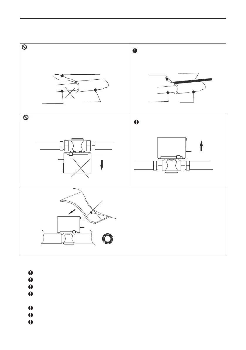
The electric wiring of the valve should be according with the Fig.25
It is prohibited to bind directly the water valve wire
and sponge up with the copper tube, as there would be
probably a short circuit or even electric leakage(as
Fig.20).
Water valve wire
Sponge
Water tube
Fig.20
The right way is letting the water valve wire
go through the pipe sleeve and then binding
the sponge and pipe sleeve up(as Fig.21).
Water valve wire
PVC pipe sleeve
Sponge
Water tube
Fig.21
It is prohibited to put the valve core upside down,
as thiswould allow the condensate water to enter or
damage the valve core and even form a short circuit
which wouldresult in a re hazard(as Fig.22).
Fig.22
The right way is placing the valve core in
the proper position and letting the leading
wire pointing at the unit(as Fig.23).
Fig.23
Sponge
It is prohibited to wrap the whole
valve with sponge, as this would
affect the heat diffusion of the
valve core and probably pose a
re hazard(as Fig.24).
Fig.24
9 Electric wiring
Before obtaining access to termingls, all supply circuits must be disconnected.
All eld supplied parts and meterials must comform to local laws and regulations.
For wiring must be performed by skilled technician.
A circuit breaker capable of shutting down power supply to the entire system and which have
at least 3mm contact seperation in each jole must be install in the xed wiring.
Earth properly.
Waring must conform to national laws and regulations.
The xed wiring must be installed with a protector with not more than 30 mA leakage current.
 Loading...