Test Operation & Troubleshooting & Maintenance
73
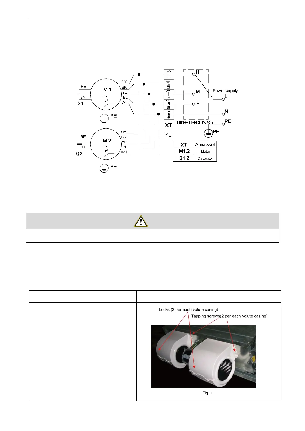
2. Electric Diagrams
FP-34WA(H)/G; FP-51WA(H)/G; FP-68WA(H)/G; FP-85WA(H)/G; FP102WA(H)/G;FP-136WA(H)/G;
FP- 170WA(H)/G; FP-204WA(H)/G; FP-238WA(H)/G; FP-34WA(H)S/G; FP-51WA(H)S/G;
FP-68WA(H)S/G; FP- 85WA(H)S/G; FP102WA(H)S/G
Notes:
①
According to actual demand, connect “M” of the three-speed switch to XT-4.
②
For FP-136wa(H)(S), Capacitor G1 is larger than capacitor G2.
③
For some models, only one motor is accessible.
④
The three-speed switch enclosed by the dotted lines is optional.
Electric wiring and piping for the FCU should be done by the qualified servicemen.
3. Replacement of Key Parts
3.1 Replacement of the Motor
①
Remove the rear volute casing.
Press the rear volute casing to release
the locks. (see Fig.1)
Take out the rear volute casing
downwards.
 Loading...