38
Installation and Maintenance
Service Manual
(1) Do not use tapped wires, stranded wires, extensioncords, or starburst connections, as they may cause overheating,
electrical shock, or re.
(2) Do not use locally purchased electrical parts inside the product. (Do not branch the power for the drain pump, etc, from
the terminal block.) Doing so may cause electric shock or re.)
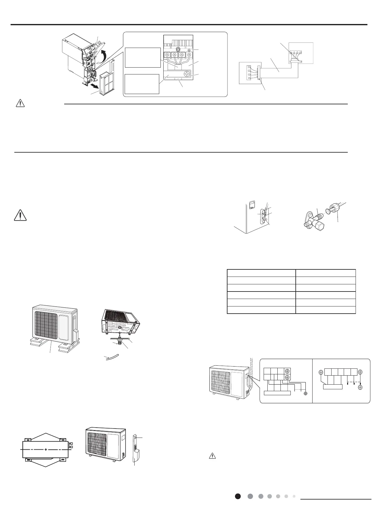
Outdoor unit
Indoor unit
Firmly fix the wires with the
terminal screws
Firmly fix the wires with the
terminal screws
When wire length exceeds 10m,
use 2.0mmdiameter wires
23
Terminal block
Electrical
component
box
Wire retainer
Use the specified wire type.
Shape wires so
N(1)
that the front metal
plate cover will fit
securely.
Firmly secure wire
retainer so that
wires sustain no
external stress.
Front metal
plate cover
Sensor securing plate
CAUTION
8.3 Outdoor Unit Installation
t least 3cm above the floor
Chassis
Drain hose
t
CAUTION
(1) Take sufcient protective measures when installing the outdoor
unit.
(2) Make sure the support can withstand at least four times the unit
weight.
(3) The outdoor unit should be installed at least 3cm above the
oor in order to install drain joint.(As show in Fig.A)
(4) For the unit with cooling capacity of 2300W~5000W, 6
expansion screws are needed; for the unit with cooling capacity of
6000W~8000W, 8 expansion screws are needed; for the unit with
cooling capacity of 10000W~16000W, 10 expansion screws are
needed.
1. Fix the Support of Outdoor Unit(Select it according to the
actual installation situation)
(1) Select installation location according to the house structure.
(2) Fix the support of outdoor unit on the selected location with
expansion screws.
2. Install Drain Joint(Only for cooling and heating unit)
(1) Connect the outdoor drain joint into the hole on the chassis.
(2) Connect the drain hose into the drain vent.(As show in Fig.B)
3. Fix Outdoor Unit
(1) Place the outdoor unit on the support.
(2) Fix the foot holes of outdoor unit with bolts.(As show in Fig.C)
handle
4. Connect Indoor and Outdoor Pipes
(1) Remove the screw on the right handle of outdoor
unit and then remove the handle.(As show in Fig.D)
(2) Remove the screw cap of valve and aim the pipe
joint at the bellmouth of pipe.(As show in Fig.E)
Fig.A
Fig.C Fig.D
Fig.F
Fig.E
Fig.B
gas pipe
Liquid pipe
Liquid
valve
gas valve
Pipe joint
(3) Pretightening the union nut with hand.
(4) Tighten the union nut with torque wrench .
5. Connect Outdoor Electric Wire
(1) Remove the wire clip; connect the power connection wire
and signal control wire (only for cooling and heating unit) to the
wiring terminal according to the color; x them with screws.(As
show in Fig.F)
Hex nut diameter(mm) Tightening torque(N
.
m)
Φ6 15~20
Φ9.52 30~40
Φ12 45~55
Φ16 60~65
Φ19 70~75
Refer to the following table for wrench moment of force
:
N
L
Indoor unit connectionPOWER
N(1)
23
yellow-
blueblue black
green
yellow-
green
brown
brown
(black)
N
L
N(1) 23 L N
brown
(black)
brown
blue
blue black
yellow-
green
yellow-
green
L
N
Indoor unit connection POWER
09、12K: 18K:
(2) Fix the power connection wire and signal control wire with
wire clip (only for cooling and heating unit).
Note: the wiring board is for reference only, please refer
to the actual one.
(1) After tightening the screw, pull the power cord slightly to
check if it is rm.
(2) Never cut the power connection wire to prolong or shorten
the distance.
Note:
 Loading...