 Loading...
Do you have a question about the Gree GPC12AL-K5NNA3A and is the answer not in the manual?
Provides an overview of the GPC12AL-K5NNA3A and GPH12AL-K5NNA3A models and their remote controller.
Details the technical parameters and performance characteristics of the air conditioning units.
Illustrates the physical dimensions and overall structure of the air conditioning units.
Depicts the flow of refrigerant in both cooling-only and cooling/heating models.
Illustrates the electrical connections for the air conditioning unit's components.
Shows the layout of components on the main and display circuit boards.
Explains the functions and operation of the unit's control panel buttons and display.
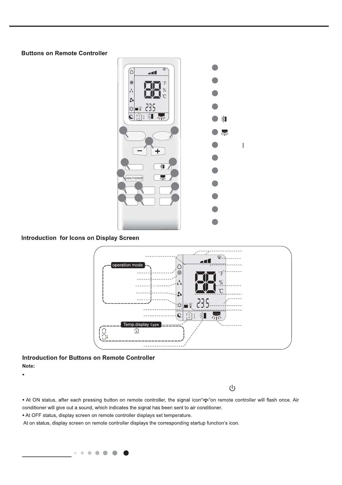
Details the buttons and icons on the remote controller for operating the unit.
Describes the basic operating modes like Cool, Heat, Fan, Auto, and their conditions.
Outlines critical safety guidelines for installation and maintenance.
Specifies precautions for selecting installation location and electrical connections.
Lists necessary accessories and tools for the installation process.
Provides step-by-step instructions for installing the unit and its components.
Instructions on how to install the wire hook for cord management.
Details methods for draining collected water from the unit.
Guide for installing the unit's window panel in a double-hung sash window.
Guide for installing the unit's window panel in a sliding sash window.
Instructions for correctly installing and removing the heat discharge pipe.
Steps to perform after installation to verify the unit's normal operation.
Information on routine maintenance, error codes, and troubleshooting.
Lists error codes displayed by the unit and their possible causes.
Provides flowcharts to diagnose and resolve common malfunctions.
Offers detailed methods for troubleshooting and repairing common issues.
Step-by-step guide to remove the front grill and filter assembly.
Instructions for removing the left and right side panels of the unit.
Details on how to detach the rear plate and associated components.
Steps to remove the top assembly of the air conditioner unit.
Guide for removing the front panel assembly of the unit.
Instructions for accessing and removing the electric box cover.
Steps for removing the third supporting board from the unit.
Guide to removing the cover protecting the propeller unit.
Instructions for detaching the evaporator assembly from the unit.
Steps for removing the second air flue assembly.
Steps for removing the first air flue assembly and water tray.
Guide to removing the supporting board and strip.
Instructions for detaching the 4-way valve interface and capillary assembly.
Steps for removing the condenser assembly.
Guide to removing the water level switch sub-assembly.
Instructions for detaching the compressor and associated fittings.
Steps for removing the motor sub-assembly (flutter).
Instructions for removing the chassis sub-assembly and caster wheels.
Provides conversion between Celsius and Fahrenheit temperature scales.
Tables correlating temperature readings with sensor resistance values.