Air-to-water Heat Pump
34
MONOBLOC
TYPE
Joints Dimension
Description Joint pipe thread
Hot water outlet of water tank 1/2″Female BSP
Circulating water inlet/outlet of water tank 3/4″Female BSP
Cooling water inlet of water tank 1/2″Female BSP
Pipe joint 3/4″Female BSP
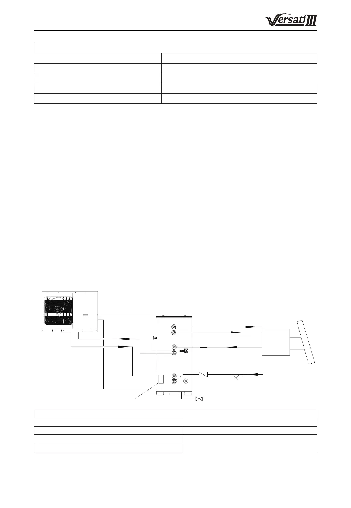
16.3 Connection of waterway system
(1) If connection between water tank and indoor unit should be through the wall, drill a hole φ70 for pass of
circulating water pipe. It is unnecessary if the hole is not needed.
(2) Preparation of pipelines: Circulating water outlet/inlet pipe must be hot water pipe, PPR pipe with nominal
out diameter of dn25 and S2.5 series (wall thickness of 4.2mm) being recommended. Cooling water inlet
pipe and hot water outlet pipe of water tank should also be hot water pipe, PPR pipe with nominal out
diameter of dn20 and S2.5 series (wall thickness of 3.4mm) being recommended. If other insulated pipes
are adopted, refer to the above dimensions for out diameter and wall thickness.
(3) Installation of circulating water inlet/outlet pipes: connect the water inlet of the unit with circulating outlet of
water tank and water outlet of unit with circulating inlet of water tank.
(4) Installation of water inlet/outlet pipes of the water tank: safety check valve, lter and cut-off valve must be
installed for the water inlet pipe according to the installation sketch of the unit. At least a cut-off valve is
needed for the water outlet pipe.
(5) Installation of blow-off pipes at the bottom of water tank: connect a piece of PPR pipe with drainage outlet
to oor drain. A cut-off valve must be installed in the middle of the drainage pipe and at the place where it is
easy to be operated by the users.
(6) After connection of all waterway pipelines, perform the leakage test rstly. After that, bind up the water
pipes, water temp sensor and wires with wrapping tapes attached with the unit.
(7) Refer to Installation Sketch of the Unit for details.
Blow-off Outlet
Tap water
Filter
Safety check
valve
Hot water output
Water Tank
Water tank temp. sensor
Cool Water
Inlet
Power cord of booster heater
Other
Thermal
System
Description Joint pipe thread
Circulating water inlet/outlet of main unit 1″Male BSP
Cooling water inlet of water tank 1/2″Female BSP
Circulating water inlet/outlet of water tank 3/4″Female BSP
Hot water outlet of water tank 1/2″Female BSP
Notes
(a) Distance between indoor unit and water tank should not exceed 5m levelly and 3m vertically. If higher,
 Loading...