82
Air to Water Heat Pump
Service Manual- Versati Series
JOTUBMMBUJPO
T-SENSOR2 CN11 terminal of temperature sensor2
T-SENSOR3 CN12 terminal of temperature sensor3
T-SENSOR4 CN13 terminal of temperature sensor4
T-SENSOR5 CN14 terminal of temperature sensor5
T-SENSOR6 CN15 terminal of temperature sensor6
DOOR-C CN23 Door detection input
OVC-HEAT3 CN28 e-heater of water tank adhesion-proof protection detector
OVC-HEAT1 CN26 e-heater of indoor unit1 adhesion-proof protection detector
OVC-HEAT2 CN27 e-heater of indoor unit2 adhesion-proof protection detector
IN-SW CN25 GHWHFWLRQLQSXWRIZDWHUÀRZVZLWFK
COM-MANUAL CN6 connect the wired controller
COM-OUT CN5 connect to outdoor unit
COM-BMS CN7 Building Management System (BMS)
TR-OUT1 CN2 transformer output 1
TR-OUT2 CN3 transformer output 2
TR-IN CN1 220V in put of transformer
CN30 CN30 heavy-current interface of end controller
CN31 CN31 heavy-current interface of end controller
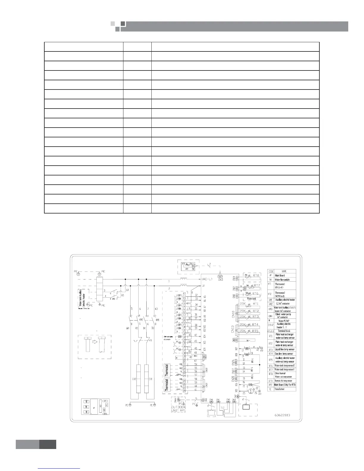
2.3 Electric Wiring Design
2.3.1 Wiring Diagram: Indoor Unit
GRS-CQ6.0Pd/Na-K(I),GRS-CQ8.0Pd/Na-K(I),GRS-CQ10Pd/Na-K(I),GRS-CQ12Pd/Na-K(I) ,GRS-
CQ14Pd/Na-K(I),GRS-CQ16Pd/Na-K(I):
XT2XT2
1920
Gate-controller
50
20 19
2 The wires in the imaninal frames
are connected by the consumer.
3 power supply for Thermostat:If it
is 230V AC,please connect Terminal
block(xt3) 21.22.23.24;If it is 24V
AC, please connect Terminal
block(xt3) 25.26.27.28.
1
N
POWER
AP
XT1
N
L
1
N(2)
2-way
valve1
2-way
valve2
3-way
valve1
3-way
valve2
Indoor Unit
Long-distance
Monitor PC
PC
Specification:
1 If there is gate control function,
pull out the leading wire 50 on
terminal boards between19 and 20
and then connect the
Gate-controller
Display
board
Communication line
Error
indicating lamp
Running
indicating lamp
 Loading...