OM-CC-G and C/2-G
7
Installation and Start-Up
WARNING
THE UNIT MUST BE INSTALLED BY PERSONNEL WHO ARE QUALIFIED TO WORK WITH GAS,
ELECTRICITY AND PLUMBING. IMPROPER INSTALLATION CAN CAUSE INJURY TO PERSONNEL AND/OR
DAMAGE TO THE EQUIPMENT. THE UNIT MUST BE INSTALLED IN ACCORDANCE WITH APPLICABLE
CODES.
CAUTION
DO NOT INSTALL THE UNIT WITH THE RIGHT SIDE VENTS BLOCKED OR WITHIN 12 INCHES OF A HEAT
SOURCE (SUCH AS A BRAISING PAN, DEEP FRYER, CHAR BROILER OR KETTLE).
DO NOT INSTALL TO THE LEFT OF ANY OPEN-FLAME EQUIPMENT. DO NOT INSTALL UNIT WITHIN FOUR
FEET OF A STEAM DRAIN.
TO AVOID DRAINAGE PROBLEMS, LEVEL THE UNIT FRONT TO BACK.
INSTALLATION MUST BE IN ACCORDANCE WITH ALL APPLICABLE CODES.
Installation
1. Mounting
Minimum rear clearance is 6" from back of oven.
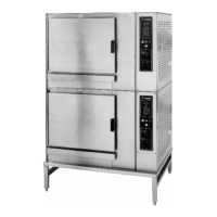
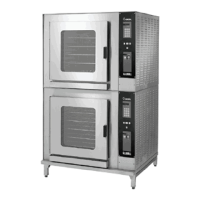
If you wish to install a Convection Combo™ on
top of another, you should obtain a double
stacked unit from the factory.
The unit must be installed in an adequately
vented room with a provision for an ample air
supply to the unit. The unit must be installed
completely under a ventilation hood, since flue
products exit the appliance over its entire depth.
Anything which might restrict the flow of air for
ventilation and combustion must be removed.
Do not obstruct the flue cover or any front, side,
top or rear vents after installation. The area
directly around the Convection Combo™ must
be cleared of all combustible material.
Installation must comply with local codes, or in
the absence of local codes, conform to the
National Fuel Gas Code ANSI Z223.1 - latest
edition, including:
“The appliance and its individual shut-off valve
must be disconnected from the gas supply
piping system during any pressure testing of that
system at test pressures in excess of ½ psig
(3.45 kPa). The appliance must be isolated
from the gas supply by closing its individual
manual shut-off valve during any pressure
testing of the gas supply piping system at test
pressures equal to or less than ½ PSI (3.45
kPa).”
2. Gas Supply Connections
WARNING
THIS UNIT IS FOR COMMERCIAL USE. NEVER
USE HOME OR RESIDENTIAL GRADE GAS
CONNECTIONS. THEY DO NOT MEET GAS
CODES AND COULD BE HAZARDOUS.
Connect to the gas supply using ½ NPT pipe for
the CC10-E and ¾ NPT pipe for the C/2-20E or
an approved equivalent. Although the immediate
connection to the Convection Combo™ is either
½ or ¾ NPT, the gas supply piping must be large
enough to provide 93,000 BTU/hour for each
CC10-G cooking chamber or 186,000 BTU/hour
for each C/2-20G cooking chamber. Supply
pressure must be at least 5" W.C. (maximum 14"
W.C.) for natural gas or 12" W.C. (maximum 14"
W.C.) for LP gas. In Canada, the installation
must conform to the Canadian Gas Code, CAN
1-B149, Installation Codes for Gas Burning
Appliances and Equipment, and/or local codes.
For units on casters, complete the gas supply
connection using only connectors that meet the
standards for movable gas appliances, ANSI
Z21.69 — latest edition. Restrain movement of
the unit by attaching a cable or chain to the
eyelet (provided at the back of the frame) and
anchoring the cable or chain to the wall or floor.
Make the length and location of the cable such
that the unit cannot pull on the gas connection
while the cable is connected.
 Loading...