English (GB)
24
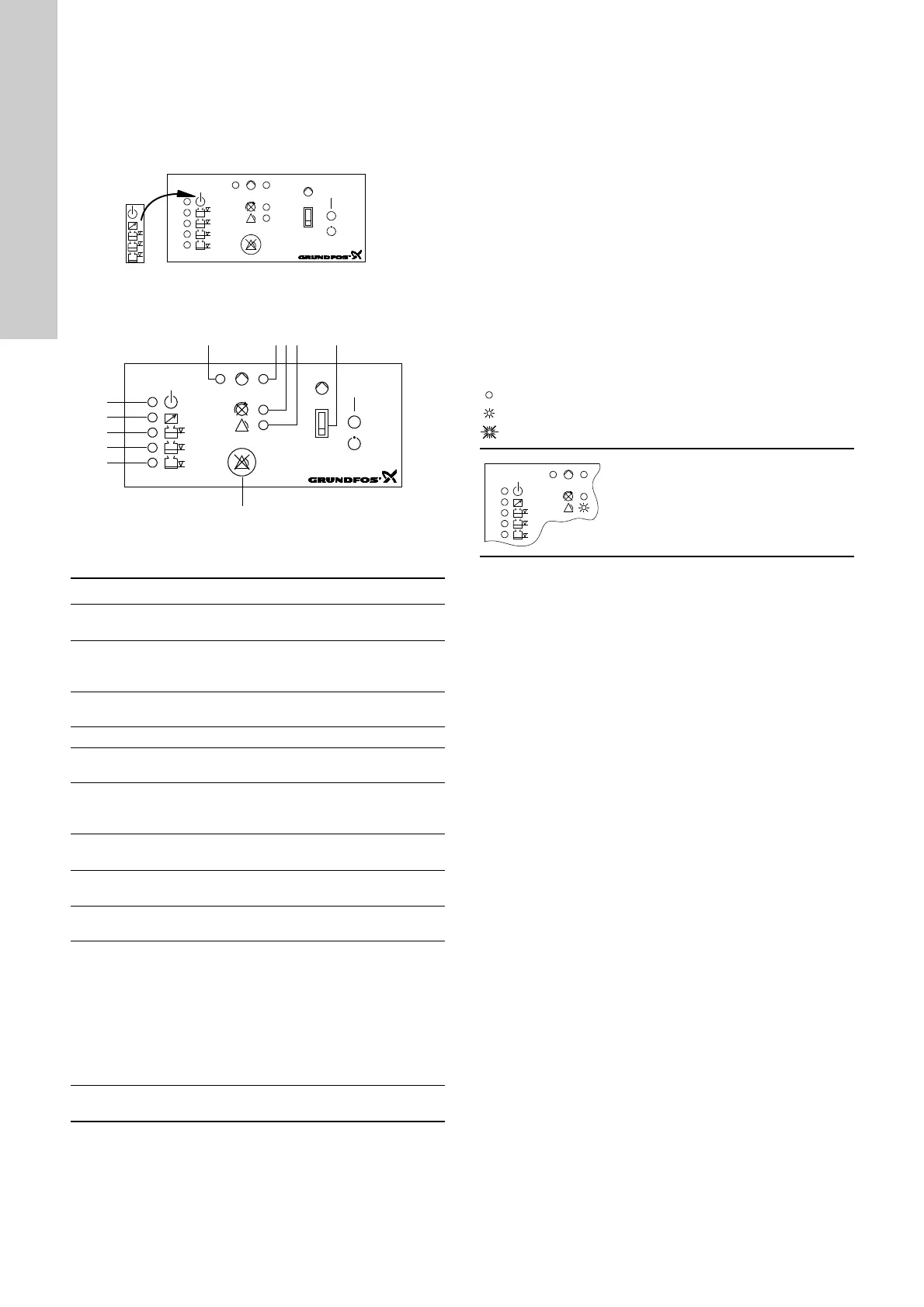
8.3 Control panel
3 electrodes, pages 45 and 46.
For these applications, the foil supplied with the LC 108 must be
attached to the CU 211 control panel as shown in fig. 20. The foil
can be found inside the LC 108 cabinet at the bottom.
Figure 20 shows how the foil is attached to the CU 211 module.
Fig. 20
Figure 21 shows the control panel of the CU 211 module.
Fig. 21
Key to the symbols in fig. 21:
8.4 Battery back-up functions
3 electrodes, pages 45 and 46.
If a back-up battery for CU 211 (accessory for certain variants) is
installed, the following functions will be carried out if the normal
electricity supply to the LC 108 fails (see also the illustrations
below):
• The common alarm is active, the red indicator light is on -
cannot be reset!
• If the external alarm device for common alarm is supplied from
an external power source, this device will be active - cannot be
reset by means of the reset button!
• The built-in buzzer (only certain variants) is activated - can be
reset by means of the reset button!
• If the starting delay function and automatic test run were
selected (switch 4 of the DIP switch), the start-up will be
delayed after the electricity supply has been switched on when
the liquid level is sufficiently high, see section 8.2.
The table below shows the situation which may occur if the
normal electricity supply to the LC 108 fails and a back-up battery
is connected:
= the indicator light is off.
= the indicator light is on.
= the indicator light is flashing.
TM01 6413 2299TM01 6424 2399
Pos. Description
1
Green indicator light, indicating starting delay (flashing)
and pump operation (permanently on).
2
Red indicator light, indicating pump fault.
Flashing: Fault in PTC resistor/thermal switch.
On: Fault in motor-protective circuit breaker.
3
Red indicator light, indicating wrong phase sequence
(only certain variants and three-phase pumps only).
4 Red indicator light, indicating common alarm.
5
ON-OFF-AUTO selector switch, three positions,
see section 8.5.
7
Reset button, push-button for manual resetting of alarm
signals to external alarm devices and the built-in buzzer
(only certain variants), see section 8.5.
8
Orange indicator light, which is activated by the
electrode for stop of pump.
9
Orange indicator light, which is activated by the
electrode for start of pump.
10
Has no function in connection with the actual
application!
11
Orange indicator light, which is activated by the
pressure switch in the discharge pipe.
The pump is stopped if the pressure is higher than the
stop pressure of the pressure switch (the indicator light
is permanently on).
The pump is started if the pressure is lower than the
starting pressure of the pressure switch and the
electrode for start of pump (see pos. 9 above) gives a
starting signal at the same time.
12
Green indicator light, indicating that the electricity
supply has been switched on.
Mains supply failure:
• The common alarm is active.
The red indicator light is on.
• The green indicator light (electricity
supply switched on) is off.
 Loading...