English (GB)
4
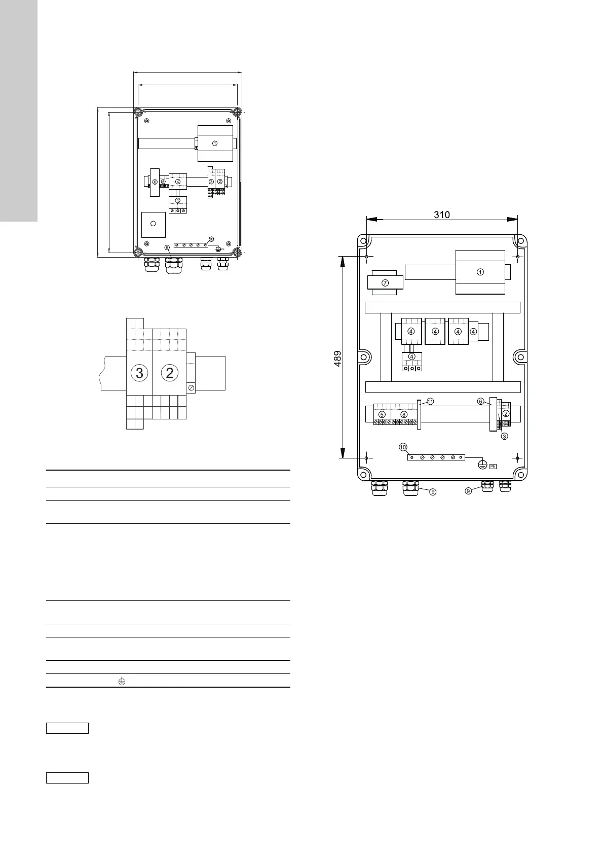
Figure 1 shows the internal construction of the LC 108 for
direct-on-line starting.
Fig. 1
Figure 2 shows the terminals listed under positions 2 and 3.
Fig. 2
Key to the symbols in figs 1 and 2:
3.3 Mounting of LC 108 for star-delta starting
Before mounting, remove the transport protectors, if any, from
inside the cabinet.
Mount the LC 108:
• on a plane wall surface,
• with the Pg cable entries pointing downwards (additional Pg
cable entries, if required, must be fitted in the bottom plate of
the cabinet),
• with four screws through the mounting holes in the back plate
of the cabinet, see fig. 3. The mounting holes must be bored
with a 4 mm bore. Fit the screws into the mounting holes and
tighten securely. Fit the plastic caps supplied with the
controller on the screws (IP65).
Figure 3 shows the internal construction of the LC 108 for
star-delta starting.
Fig. 3
TM01 6867 2308TM01 6868 2308
Pos. Description
1 Module CU 211.
2
Terminal block for level inputs
(11-12, 21-22, 31-32, 41-42).
3
Terminal block with:
• input for the PTC resistance/thermal switch of the
motor (T11-T21),
• output for external alarm device for high-level alarm
(H-NC, H-COM, H-NO) (only certain variants),
• output for external alarm device for common alarm
(G-NC, G-COM, G-NO).
4
Motor protection relay (contacts and thermal relay
fitted).
5 Terminal block for electricity supply.
6
Fuse holders for control circuit fuses (1 to 3 depending
on voltage/current variant).
9 Pg cable entries.
10 Earth bar (
PE
).
If the distance between the controller and pit
exceeds 20 metres, it is not advisable to use
electrodes as problems with the signal values sent
back to the controller may arise.
In such cases, it is recommended to use float
switches.
Cables of up to 100 metres can be connected
between the controller and the float switches.
T11 T12
1211
22
32
42
21
31
41
G-NO
H-NO
G-COM
H-COM
G-NC
H-NC
TM01 7872 2308
 Loading...