English (GB)
30
10. Systems for drainage applications
Description (see also page 49 or 50):
The pump is controlled by the flow switch, pos. 2, in the discharge
pipe.
• The pump is stopped when the flow switch does not register
any liquid flow.
• After a stop signal, the pump will attempt to restart when the
"restarting time" (can be set) has expired. The restarting
attempt will be interrupted if the flow switch does not register
any liquid flow before the expiration of the "dead time" (can be
set).
• The switch for manual restarting, pos. 1, will initiate a
restarting attempt when the switch is set to position on
(restarting).
10.1 Electrical connection
Drainage application, pages 49 and 50.
Fig. 13 on page 49.
The figures show all electrical connections required to connect
the LC 108 for direct-on-line starting, drainage application, flow
switch.
Fig. 14 on page 50.
The figure shows all electrical connections required to connect
the LC 108 for start-delta starting, drainage application, flow
switch.
The operating voltage and frequency are marked on the controller
nameplate. Make sure that the controller is suitable for the
electricity supply on which it will be used.
All cables/wires must be fitted through the Pg cable entries and
gaskets (IP65).
Maximum back-up fuse is stated on the controller nameplate.
If required according to local regulations, an external mains
switch must be installed.
Single-phase motors must be connected to an external operating
capacitor and in certain cases also to a starting capacitor.
Further details can be found in the installation and operating
instructions for the pump in question.
The switch for manual restarting, pos. 1, must be connected as
an NC contact.
The flow switch, pos. 2, must be connected as an NO contact.
Key to the symbols in fig. 13 on page 49 and fig. 14 on
page 50:
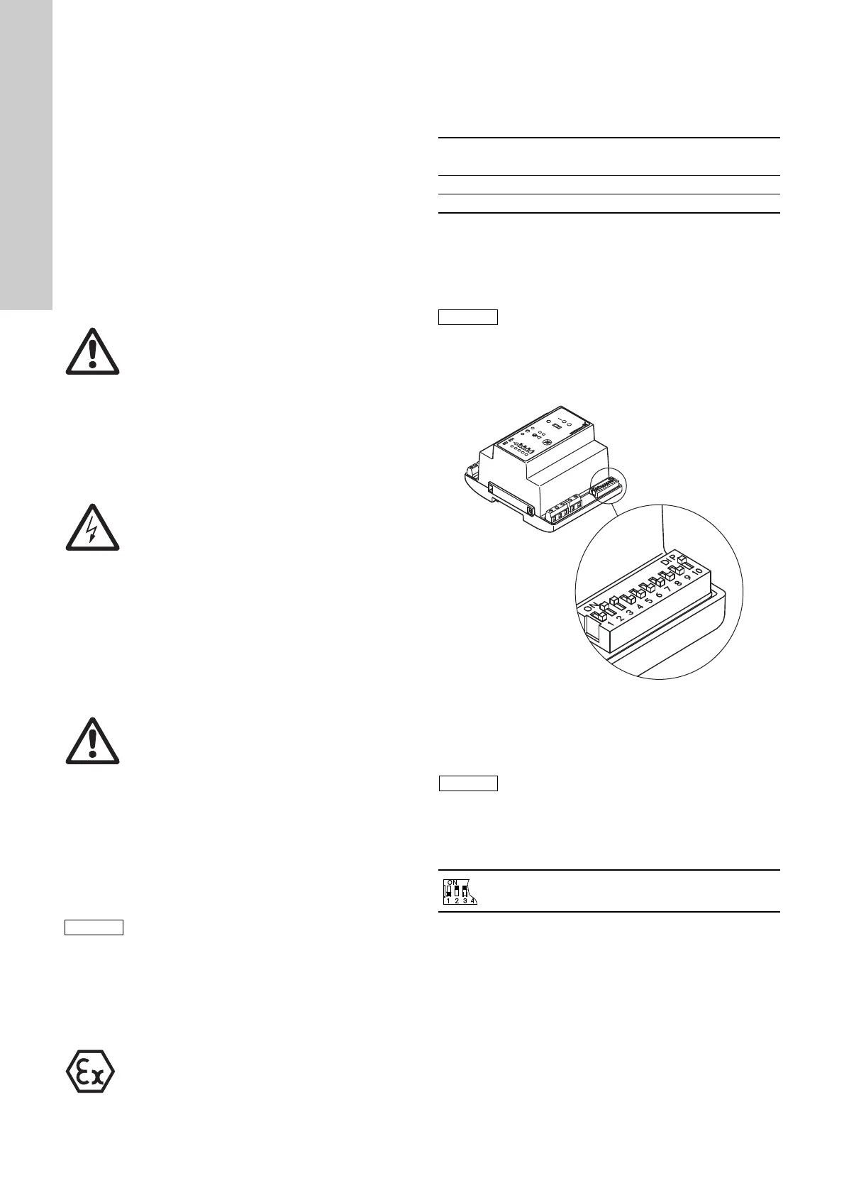
10.2 Setting
Drainage application, pages 49 and 50.
The CU 211 module has a 10-pole DIP switch in the bottom right
corner, see fig. 26.
The DIP switch setting offers the following possibilities:
• setting of dead time (switches 4, 5 and 6),
• setting of restarting time (switches 7, 8, 9 and 10).
Fig. 26
Set the DIP switch as shown in fig. 26.
Each individual switch (1 to 10) of the DIP switch can be set to
position OFF or ON.
Set the switches 1 to 10 as follows:
• Switches 1, 2 and 3, application type:
When the DIP switch setting is changed, the controller must
be switched off for at least 1 minute!
Warning
Before starting any work on pumps used to pump
liquids which could be constituted as being
hazardous to health, thorough cleaning/venting of
pumps, pits, etc. must be carried out according to
local regulations.
Before making any connections in the LC 108 or
work on pumps, pits, etc., it must be ensured that the
electricity supply has been switched off and that it
cannot be accidentally switched on.
Warning
Before starting work on the system, switch off the
supply voltage and lock the mains switch in position
0.
Any external voltage connected to the system must
be switched off before work is started.
Warning
The LC 108 must be connected in accordance with
the rules and standards in force for the application in
question.
If the PTC resistance/thermal switch of the motor is
connected, the factory-fitted short-circuit jumper
must be removed (terminals T11-T21).
Warning
LC 108 must not be used for drainage applications
(pages 49 and 50) in explosion hazard areas as the
motor will restart automatically after the PTC
resistance/thermal switch in the motor has caused a
cutout. However, the motor will not restart until it has
cooled to normal temperature.
Pos. Description
Terminal
number
1 Switch for manual restarting. 41-42
2 Flow switch. 11-12
The controller must be off circuit to ensure the
correct configuration during start-up after change of
the DIP switch setting.
TM04 2345 2308
The DIP switch must not be set to other switch
combinations than those described in this section.
This setting determines the actual application type
(drainage application, pages 49 and 50).
 Loading...