English (GB)
31
• Switches 4, 5 and 6, dead time:
When the DIP switch setting is changed, the controller must
be switched off for at least 1 minute!
• Switches 7, 8, 9 and 10, restarting time:
When the DIP switch setting is changed, the controller must
be switched off for at least 1 minute!
* At the setting "no restarting", the pump can only be restarted by
means of the switch for manual restarting.
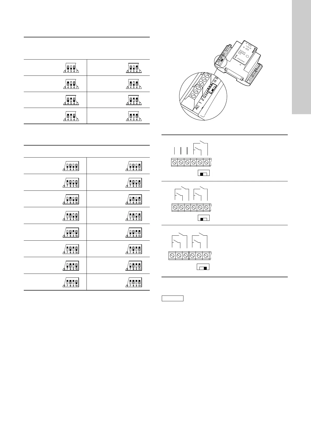
AC/DC selector:
The AC/DC selector switch for electrodes and/or float switches is
placed as shown in fig. 27.
Fig. 27
The dead time is the time the pump is allowed to run after
starting without a liquid flow being registered by the flow switch.
The pump will be stopped again if the flow switch does not
registers any liquid flow.
10 sec. 2 min.
20 sec. 3 min.
40 sec. 4 min.
1 min. 5 min.
The restarting time is the time from the last stop signal until the
pump attempts to restart.
No restarting* 15 min.
1 min. 17 min.
2 min. 20 min.
3 min. 25 min.
5 min. 30 min.
7 min. 50 min.
10 min. 70 min.
12 min. 90 min.
TM02 5747 3902
Operation with electrodes and
float switches:
Selector switch in position AC:
It is possible to connect
3 electrodes (1 as reference
electrode) and 2 float switches.
The controller transmits a
13-18 VAC signal.
Operation with float switches:
Selector switch in position AC:
It is possible to connect 4 float
switches.
The controller transmits a
13-18 VAC signal.
Operation with float switches:
Selector switch in position DC:
It is possible to connect 4 float
switches.
Cables of up to 100 metres can be
connected between the controller
and the float switches.
The controller transmits a 12 VDC
signal.
If the distance between the controller and pit
exceeds 20 metres, it is not advisable to use
electrodes as problems with the signal values sent
back to the controller may arise.
In such cases, it is recommended to use float
switches.
AC 1 2
13-18 VAC
0 V
AC
DC
G3 4
AC 1 2
13-18 VAC
0 V
AC
DC
G3 4
 Loading...