English (GB)
7
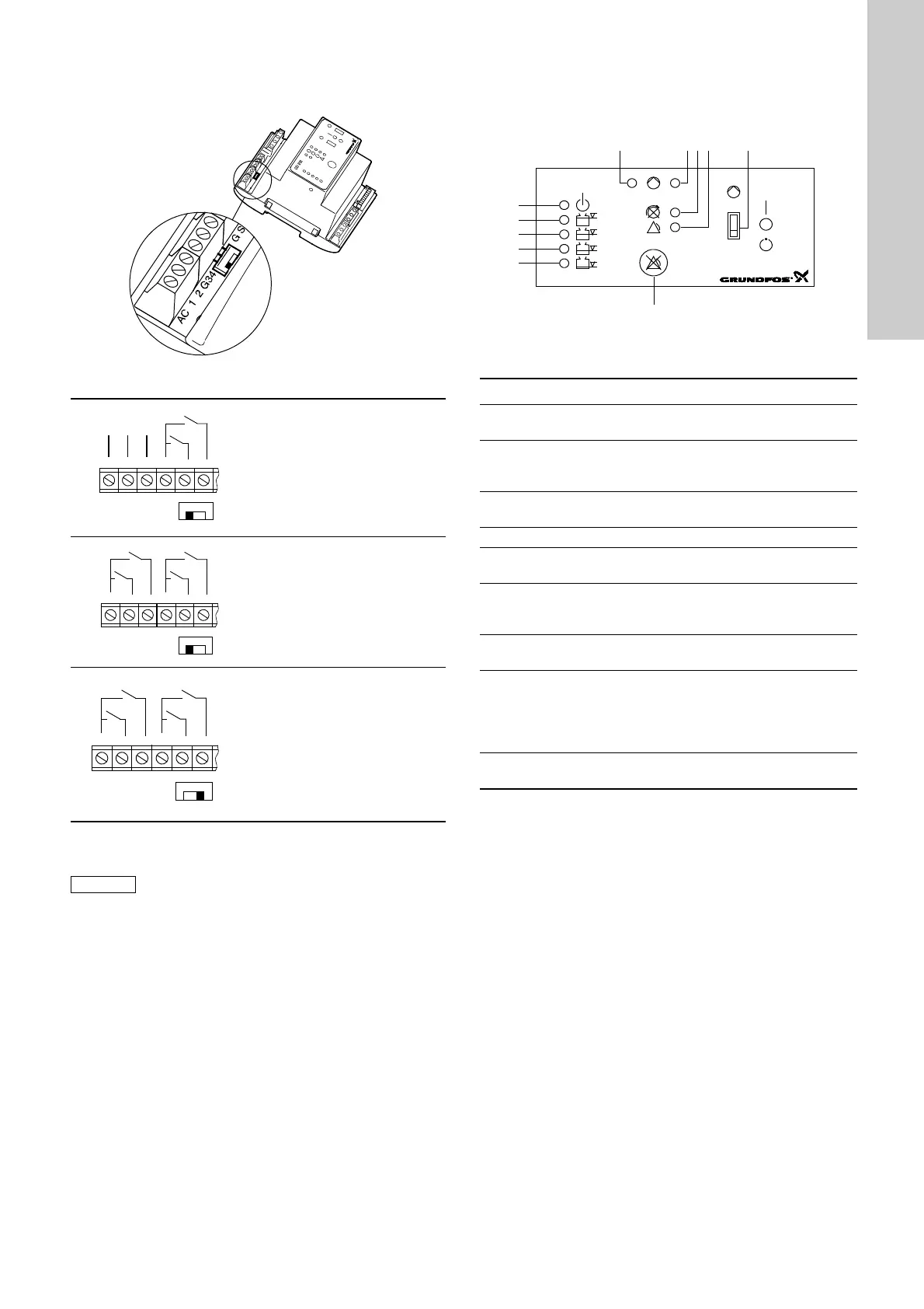
AC/DC selector:
The AC/DC selector switch for electrodes and/or float switches is
placed as shown in fig. 6.
Fig. 6
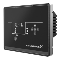
4.3 Control panel
2 float switches, pages 37 and 38.
Figure 7 shows the control panel of the CU 211 module.
Fig. 7
Key to the symbols in fig. 7:
TM02 5747 3902
Operation with electrodes and
float switches:
Selector switch in position AC:
It is possible to connect
3 electrodes (1 as reference
electrode) and 2 float switches.
The controller transmits a
13-18 VAC signal.
Operation with float switches:
Selector switch in position AC:
It is possible to connect 4 float
switches.
The controller transmits a
13-18 VAC signal.
Operation with float switches:
Selector switch in position DC:
It is possible to connect 4 float
switches.
Cables of up to 100 metres can be
connected between the controller
and the float switches.
The controller transmits a 12 VDC
signal.
If the distance between the controller and pit
exceeds 20 metres, it is not advisable to use
electrodes as problems with the signal values sent
back to the controller may arise.
In such cases, it is recommended to use float
switches.
AC 1 2
13-18 VAC
0 V
AC
DC
G3 4
AC 1 2
13-18 VAC
0 V
AC
DC
G3 4
TM01 6425 3902
Pos. Description
1
Green indicator light, indicating starting delay (flashing)
and pump operation (permanently on).
2
Red indicator light, indicating pump fault.
Flashing: Fault in PTC resistor/thermal switch.
On: Fault in motor-protective circuit breaker.
3
Red indicator light, indicating wrong phase sequence
(only certain variants and three-phase pumps only).
4 Red indicator light, indicating common alarm.
5
ON-OFF-AUTO selector switch, three positions,
see section 4.5.
7
Reset button, push-button for manual resetting of alarm
signals to external alarm devices and the built-in buzzer
(only certain variants), see section 4.5.
8
Orange indicator light, which is activated by the float
switch for start/stop of pump.
9, 10
and
11
3 orange indicator lights, which are activated by the float
switch for high-level alarm.
In case of high-level alarm, the top indicator light is
flashing and the two other indicator lights are
permanently on.
12
Green indicator light, indicating that the electricity supply
has been switched on.
 Loading...