English (GB)
9
7. Assembly of MS6000
Assemble the motor when the parts have been cleaned and
checked, and the defective parts have been replaced with new
ones.
1. Place the stator housing, pos1, vertical in the jaws, pos. L,
and tighten.
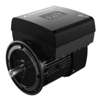
2. Fit the aligning bracket, pos. T, over the motor head, using two
of the threaded holes and the belonging screws, pos 22.
Make sure that there is 10 mm gap between the bracket and
the motor head. See fig. 4.
Fig. 4 Aligning bracket on motor head
3. Turn the stator housing to horizontal position.
4. Fit the upthrust ring, pos. 2a, on the D-end of the rotor, pos, 2.
5. Carefully insert the rotor into the stator housing from the
ND-end until it stops at the bracket, pos. T.
6. Tighten the two screws, pos. 22, holding the bracket.
By doing so, the rotor is being pushed back, but the upthrust
ring will stay fixed in the correct position inside the stator
housing.
7. Turn the stator housing to vertical position with the ND-end
facing up.
8. Insert the radial bearing pos. 4, into the stator housing.
9. Insert the clamping flange, pos. 7a.
Make sure that the holes of the clamping flange are aligned
with the threaded holes in the stator housing.
10. Insert the stop for bearing bracket(s), pos. 42.
11. Fasten the bracket(s) and clamping flange with the four
screws, pos. 41. See section 3. Tightening torques and
lubricants.
Depending on the size of the thrust bearing, there are different
types and numbers of brackets. See fig. 5, 6 and 7.
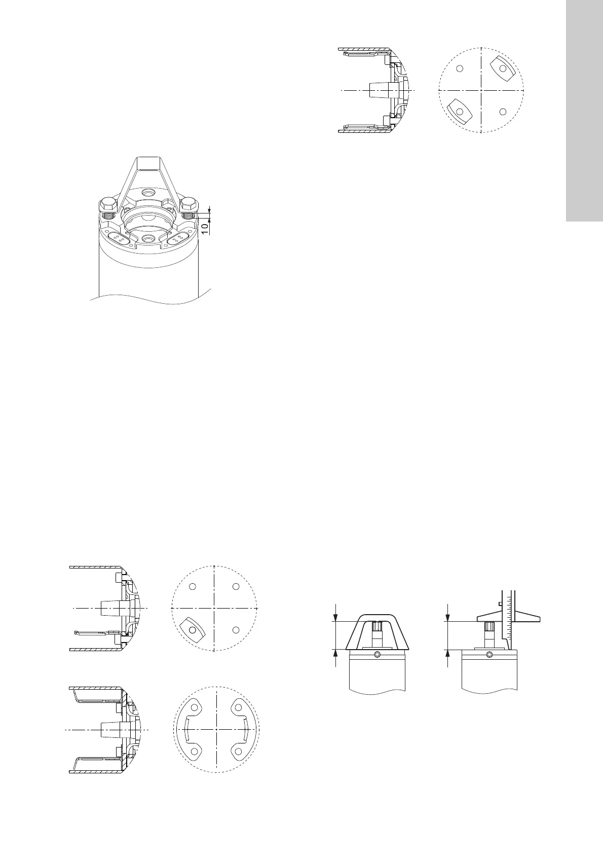
Fig. 5 Bracket for 7.5 kN thrust bearing
Fig. 6 Brackets for 27 kN thrust bearing
Fig. 7 Brackets for 40 kN thrust bearing
12. Fit the rotating part of the thrust bearing, pos. 6, onto the
shaft.
13. Position a space e.g a wooden block between the D-end of
the shaft and the bracket, so the shaft is moved a bit back.
14. Use a plastic mallet, pos. I, and a punch, pos. R or S, to fix the
rotating part on the conus of the shaft.
Note: It is important that the rotating part is fixed with one
hard hit. Failing this, the rotating part may not be knocked all
the way home on the conus. Consequently the shaft height
will change over time, and the thrust bearing can be
damaged.
15. Fit the stationary part of the thrust bearing, pos. 3, into the
stop for bearing bracket(s), pos. 42.
Note: As the 40 kN can be difficult to fit, we recommend that
you use two screwdrivers to push the bracket to the side and
manoeuvre the thrust bearing into place.
16. Loosen the lock screw in the shaft adjustment unit, pos. 45,
and fit it into the stator housing.
17. Secure the shaft adjustment unit with a spring retainer, pos.
49.
Note: Before you fit the retainer spring, clean the recess as it
is important that the retainer spring has full contact with the
bottom of the recess.
18. Insert the clamping flange, pos. 7, into the stator housing.
Note: Make sure that the innermost holes are aligned with the
holes in the shaft height adjustment unit.
19. Fasten the clamping flange with four screws, pos. 48, and
cross-tighten with the specified torque, using a torque
screwdriver, pos. AB. See section 3. Tightening torques and
lubricants.
20. Press the shaft backwards and turn the stator housing 180° in
the jaws so the D-end is facing upwards.
21. Remove the bracket, pos. T.
22. Check the shaft height using a depth gauge, pos. K, or a shaft
height gauge, pos. Z.The shaft height must be within 72.8 ±
0.2 mm. See fig. 8.
Note: When using the depth gauge, beware that the shaft end
is conceal shaped. Make sure that the depth gauge is square
on the motor head and shaft end
Fig. 8 Checking of shaft height
TM05 9768 4413TM06 0441 0514TM06 0443 0514
TM06 0444 0514TM06 0598 0514
72.8
 Loading...