Inrush current
All electronic pumps contain electronic units that must be
protected by filters, including capacitors and ECM pumps
frequency converters with AC/DC rectifiers containing
capacitors, to equalize the waves. This is not the case in
most asynchronous pumps.
TM060822
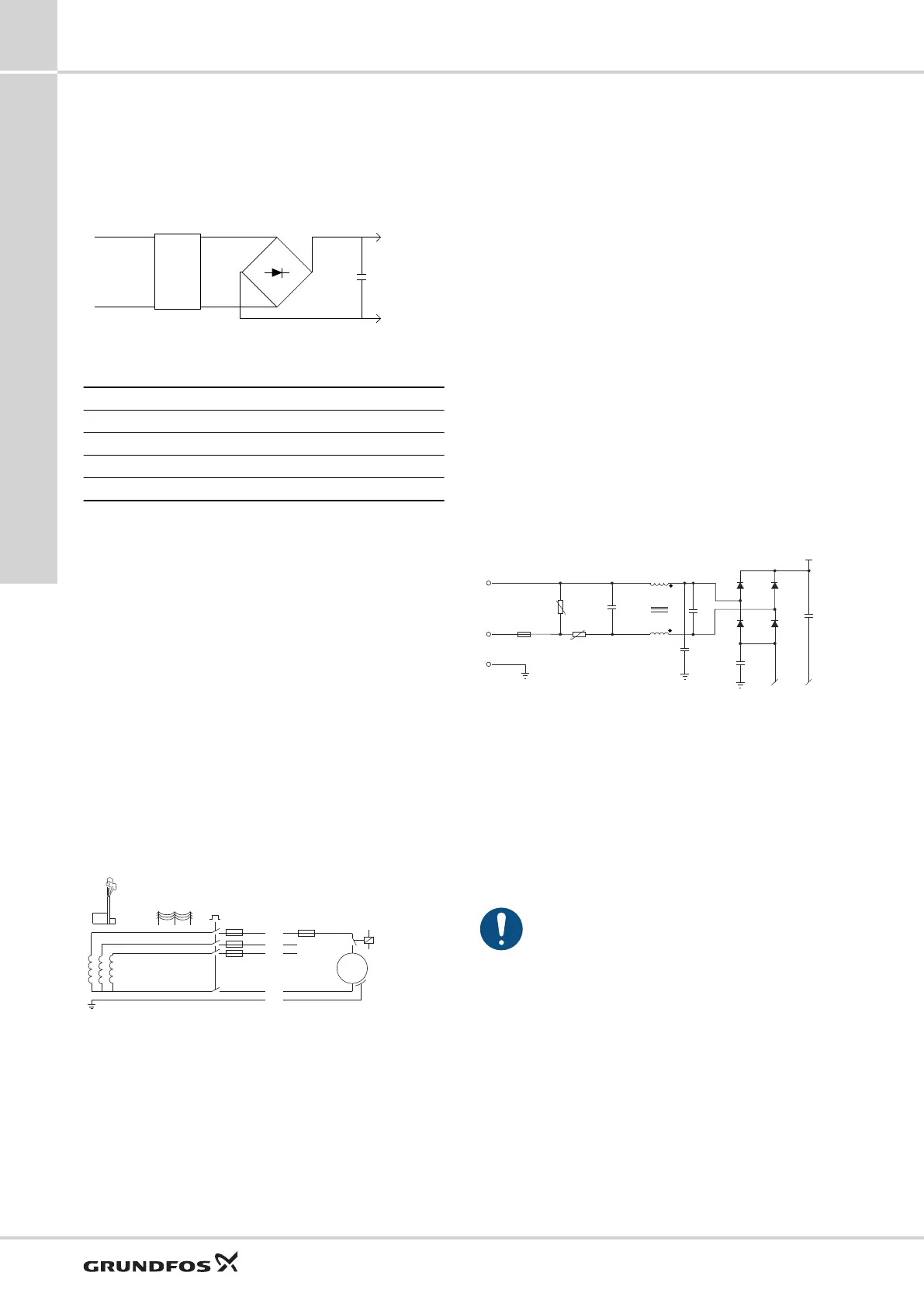
Rectification of VAC voltage to DC voltage
Pos. Description
A Mains
B EMC filter
C Rectifier
D Bulk capacitor
The load of electronically commutated motors (ECM)
behaves as a capacitive load and not as a motor load like
in a standard pump.
At start, the capacitor is unloaded. Hereby the amplitude
of the current peak depends on the grid impedance, until
the capacitor is charged. The faster the capacitor is
charged, the higher amplitude, and the faster the pump
can be started. After this period of time, the current will
drop to the rated current.
Definition: Inrush current is the current peak charging the
capacitors in the electronics when the supply voltage is
connected.
Note: When discussing measurements, it is important to
refer to the same method. Since 2007, Grundfos uses the
IEC 61000-3-3 Annex B method for measuring inrush
current.
The inrush current peak charges the bulk capacitor to 325
VDC as fast as the power grid allows. That shows that
inrush current is not only depending on the integrated
electronics but as well on the impedance of the grid.
TM060819
If you use a relay to switch the power supply of the pump,
you risk excessive wear on the relay contact surface.
To avoid such problems, there are various external and
internal solutions.
External solutions in the controller of the
appliance unit
• Specific relays with silver tin oxide (AgSnO
2
) inrush
relay contacts.
• Switching at ZERO crossing.
• Standby operation - pump only switches via the PWM
signal.
Internal solutions in the pump
• NTC resistor in the power input circuit (passive)
• Bypass relay with PTC resistor or solid state inrush
reduction controlled by the electronics (active)
UPM3 pumps are available with different hardware:
Related information
NTC resistor (passive option)
Relay and PTC (active - standard for UPM3 HYBRID
variants)
NTC resistor (passive option)
We recommend that you use this option for pumps that
are permanently connected to the grid and switched on/off
by external PWM signal.
EARTH EARTH
EARTH
GND GND
EARTH
VDR3
F1
NTC1
L
N
1 2
C43
2 1
3 4
L1
C14
C3
C4
D13 D15
D14D11
+
C6
DC+
TM060820
NTC option
At startup the operating temperature of the pump
including the NTC resistor is cold. In this situation the
NTC resistor has a high resistance and is able to limit the
inrush current down to ~ 10 A.
During operation the operating temperature of the pump
including NTC resistor is hot. There is no inrush current
but the NTC resistance decreases so that the loss is
limited.
At restart, the operator must ensure that the NTC
resistor has been cooled down so that efficient
operation is guaranteed. Normally, it takes 1 minute to
cool down the resistor.
When the power supply to the pump is switched on and
off via an external relay, you must ensure that the contact
material of the relay is able to handle higher inrush
currents.
Related information
Internal solutions in the pump
Relay and PTC (active - standard for UPM3 HYBRID
variants)
UPM3
11
50
Electrical installation

 Loading...