English (GB)
12
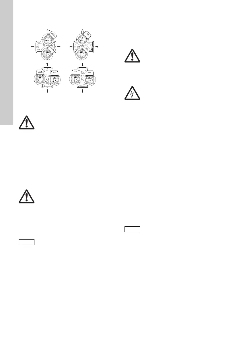
Possible flow directions for twin-head pumps,
see fig. 8.
Fig. 8 Flow directions, twin-head pumps
Change the terminal box position as follows:
1. Remove the four screws holding the pump head.
2. Turn the pump head to the desired position.
3. Refit the four screws and tighten securely.
When changing the terminal box position of twin-
head pumps, it may be necessary to remove the
cable connecting the two terminal boxes. It is
advisable to disconnect the cable from pump 1.
Do not start the pump until the system has been filled
with liquid and vented. Furthermore, the required
minimum inlet pressure must be available at the
pump inlet. See page 330.
To change the nameplate position, ease the outer
edge of the nameplate at the cutout with a
screwdriver, turn the nameplate to the new position,
and push it into place.
5.4 Frost protection
If the pump is not being used during periods of frost,
the necessary steps must be taken to prevent frost
bursts.
6. Electrical connection
The electrical connection must be carried out
according to local regulations.
Check that the supply voltage and frequency
correspond to the values stated on the nameplate.
The thermal overload switch must be adjusted to the
pump full-load current (stated on the pump
nameplate) according to the speed selected.
See fig. 20 at the end of these instructions.
Earthing or neutralisation can be used for protection
against indirect contact. A current- or voltage-
operated earth-leakage circuit breaker can be used
as extra protection.
6.1 Single-head and twin-head pumps with
standard module
The pump must be connected to the power supply
via an external contactor.
The contactor must be connected to the thermal
overload switch incorporated in the pump, terminals
T1 and T2, to protect the pump against overloading
at all three speeds.
Figures 12 and 13 at the end of these instructions
show the possible connections:
• Fig. 12 shows the electrical connections when
using external impulse contacts for start/stop.
• Fig. 13 shows the electrical connections when
using an external changeover contact for start/
stop.
TM02 1399 2701
Warning
Before the screws are removed,
the system must be drained,
or the isolating valves on either side of
the pump must be closed, as the
pumped liquid may be scalding hot and
under high pressure.
Warning
Never make any connections in the
pump terminal box unless the power
supply has been switched off.
When the terminal box position has
been changed, the pump nameplate
must be turned so that the cutout
points downwards. This allows water
from a possible venting to escape.
Warning
Never make any connections in the
pump terminal box unless the power
supply has been switched off.
The pump must be earthed.
The pump must be connected to an
external mains switch with a minimum
contact gap of 3 mm in all poles.
Warning
It must be possible to lock the main
switch in the off position.
Type and requirements as specified in
EN 60204-1, 5.3.2.
If the pump is also protected by a
motor-protective circuit breaker, this
circuit breaker must be set to the
current consumption of the pump at
the selected speed. The motor-
protective circuit breaker setting must
be changed every time the pump speed
is changed. The current consumption
at the individual speeds is stated on
the pump nameplate.
 Loading...