English (GB)
13
6.2 Twin-head pumps with relay module
The pump is connected directly to the mains as it
incorporates overload protection at all three speeds.
The pumps are factory-set to alternating operation
as duty and standby pump. Pump change takes
place every 24 hours.
Figures 14 to 16 at the end of these instructions
show the possible connections and the setting of the
selector switch for the various operating modes.
• Fig. 14: Alternating operation.
• Fig. 15: Standby operation with pump 1 as duty
pump and pump 2 as standby pump.
• Fig. 16: Standby operation with pump 2 as duty
pump and pump 1 as standby pump.
In the case of single-pump operation, the cable
between the pumps is to be removed. The pumps
must be set individually and connected separately to
the mains. See figs 17 and 18:
• Fig. 17: Electrical connection and setting of the
selector switch when using the signal output for
operating indication.
• Fig. 18: Electrical connection and setting of the
selector contact when using the signal output for
fault indication.
Fault or operating indication for twin-head
pumps in alternating operation
If the signal output is to be used for fault or operating
indication, an intermediate relay must be used.
Figure 19 shows a single-phase pump in alternating
operation with external fault indication if pump 2 or
both pumps are faulty.
Fault or operating indication for twin-head
pumps in standby operation
If the signal output of the duty pump is to be used
for fault or operating indication, an intermediate relay
must be used.
If the signal output of the standby pump is to be
used for fault or operating indication, proceed as
shown in fig. 17 or 18.
6.3 Frequency converter operation
We do not recommend the UPS and UPSD pumps
for frequency converter operation for the following
reasons:
• The noise level will increase.
• The life of the motor insulation system will be
reduced due to voltage peaks caused by the
frequency converter.
• On three-phase pumps, the indication of the
indicator light will be wrong. It will always be red.
• Pumps fitted with protection or relay module must
not be connected to a frequency converter.
We recommend Grundfos MAGNA and
UPE Series 2000 which have built-in frequency
converter.
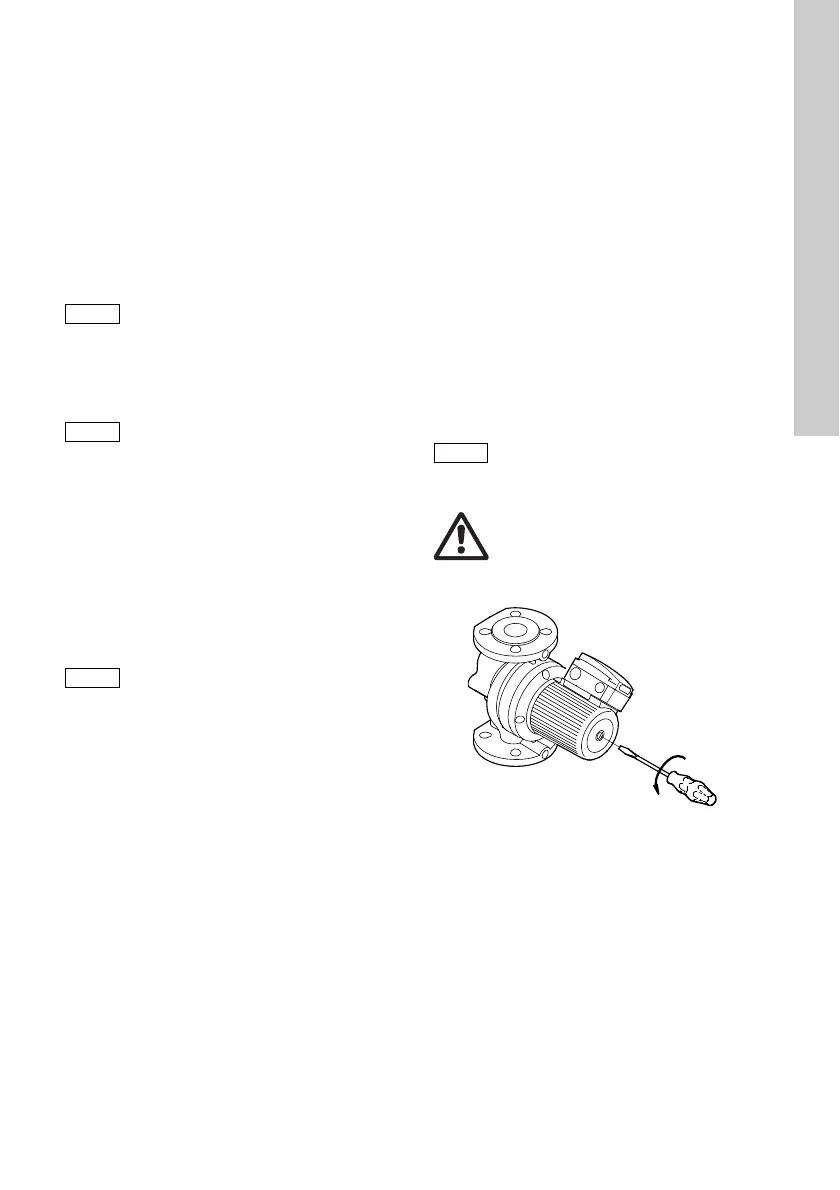
7. Start-up
Do not start the pump until the system has been filled
with liquid and vented. Furthermore, the required
minimum inlet pressure must be available at the
pump inlet. See page 330.
Fig. 9 Venting the pump
The selector switch of pump 2 must
have been set to either fault or
operating indication in this operating
mode.
The selector switch of pump 1 must
have been set to either fault or
operating indication in this operating
mode.
In the case of single-pump operation,
the selector switch must be set to
either fault or operating indication.
The system cannot be vented through
the pump.
Warning
If the inspection screw (fig. 9) is to be
slackened, care should be taken to
ensure that the escaping, scalding hot
liquid does not cause personal injury
or damage to components.
TM02 1405 1101
 Loading...