EasyManua.ls Logo

Hach Polymetron 9500 User Manual

Hach Polymetron 9500
50 pages
To Next Page IconTo Next Page
To Previous Page IconTo Previous Page
Page #24 background imageLoading...
Page #24 background image
Graphical display
The graph shows concentration and temperature measurements for each channel in use. The graph
supplies easy monitoring of trends and shows changes in the process.
1. From the graphical display screen use the up and down arrow keys to select a graph and push
the home key.
2. Select an option:
Option Description
MEASUREMENT VALUE Set the measurement value for the selected channel. Select between AUTO
SCALE and MANUALLY SCALE. For manual scaling enter the minimum and
maximum measurement values.
DATE & TIME RANGE Select the date and time range from the available options.
System startup
When initially powered up, the LANGUAGE, DATE FORMAT and DATE/TIME screens appear in
order. After these options are set, the controller performs a device scan and displays the message
SCANNING FOR DEVICES. PLEASE WAIT... If a new device is found, the controller performs an
installation process before displaying a main measurement screen.
If the scan finds previously installed devices without configuration changes, the main measurement
screen of the device in the number one position appears immediately after the scan is complete.
If a device has been removed from the controller or is not found during the next power-cycled or
menu-driven scan, the controller displays a DEVICE MISSING message and prompts to delete the
missing device.
If no sensor is connected to an installed analog module, the controller will indicate an error. If devices
are connected but not found by the controller, refer to the Troubleshooting section of this manual.
Set the language, date and time for the first time
The controller displays the language, date and time edit screens when the controller is powered on
for the first time, and when it is powered on after the configuration settings have been set to their
default values.
After the language, date and time options are set for the first time, update the options as necessary
through the setup menu.
1. In the LANGUAGE screen, highlight a language in the options list and push the enter key.
English is the default language for the controller.
2. In the DATE FORMAT screen, highlight a format and push the enter key.
3. In the DATE/TIME screen, push the right or left arrow keys to highlight a field, then push the up
and down arrow keys to update the value in the field. Update the other fields as necessary.
4. Push the enter key. The changes are saved and the controller performs a start-up scan for
devices. If connected devices are found, the controller displays the main measurement screen for
the device in the number one position. If the controller fails to find connected devices, refer to the
Troubleshooting section of this manual.
Controller configuration information
General information about configuration options is listed in the table.
1. Push the menu key and select Polymetron 9500 SETUP.
Option Description
SECURITY SETUP Sets the passcode preferences.
OUTPUT SETUP Configures the controller analog outputs.
22 English

Table of Contents

Other manuals for Hach Polymetron 9500

Question and Answer IconNeed help?

Do you have a question about the Hach Polymetron 9500 and is the answer not in the manual?

Hach Polymetron 9500 Specifications

General IconGeneral
BrandHach
ModelPolymetron 9500
CategoryController
LanguageEnglish

Summary

Product Specifications

General Information

Provides general details about the controller, including liability and modification rights.

Key Technical Parameters

Details operating/storage temps, enclosure, power, outputs, relays, dimensions, and communication.

Safety Information

Hazard and Warning Symbols

Explains hazard symbols (Danger, Warning, Caution, Notice) and precautionary labels for safe operation.

Installation Procedures

Mounting and Enclosure Details

Covers controller enclosure and mounting options, detailing physical installation aspects.

Wiring and Connections

Wiring Overview

Provides a general diagram and labels for internal controller wiring connections.

Wiring for Power

Details safety warnings and procedures for connecting the controller to AC or DC power sources.

User Interface and Navigation

Keypad and Controls

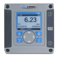
Details the controller's keypad layout, including menu, home, back, enter, and directional keys.

SD Card Installation

Provides instructions and figures for installing a Secure Digital (SD) memory card into the controller.

System Startup and Configuration

Initial Setup Procedures

Covers setting language, date, and time for the first-time controller setup.

Controller Configuration Options

Details how to access and configure settings like security and outputs.

Advanced Operation

Security Setup

Explains how to enable, disable, and edit the controller's passcode for security.

Analog Input Module Configuration

Guides on setting up analog input modules for 0-20 mA or 4-20 mA signals.

Analog Output Configuration

Details how to assign and configure the controller's analog outputs and their functions.

Relay Setup and Functions

Explains how to configure relays for alarm, scheduler, and feeder control functions.

Discrete Input Setup

Guides on configuring the controller's discrete input channels for various logic levels.

Calculation Setup

Details how to set up calculations using two sensors and mathematical functions.

Maintenance

Cleaning and Component Replacement

Provides instructions for cleaning the controller and notes on fuse/battery replacement.

Troubleshooting

Output and Relay Problems

Lists problems like no/incorrect output or relay activation and their resolutions.

SD Card and Display Issues

Addresses SD card recognition, display problems, and power-up issues.

Module Recognition and Device Errors

Covers issues with modules not recognized, missing devices, and error messages.

Replacement Parts and Accessories

General Accessories

Lists general replacement parts and accessories like SD cards, cables, and kits with item numbers.

Test and Maintenance Menu

Device Scanning and Output Calibration

Details functions for scanning devices and calibrating mA outputs.

Output Testing and Status

Explains how to test output signals, view status, and manage relays.

Warning and Error Conditions

Acknowledging Controller Warnings

Provides steps to acknowledge controller warnings and error messages.

Device Scan Messages

Explains messages related to device installation, missing devices, and scan status.

Related product manuals