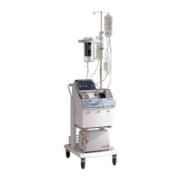
System Description 2-5
P/N 39551-00, Rev. F
c. INPUT POWER RECEPTACLE. This machine component allows the con-
nection to the power cord.
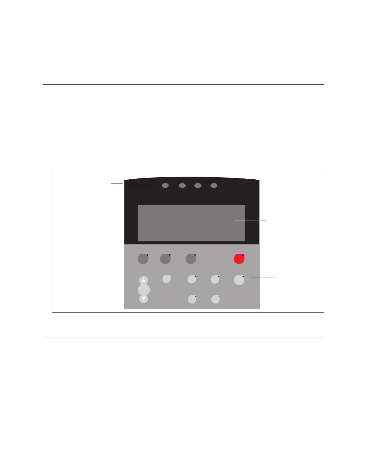
USER PANEL
The MCS+ device is operated through the User Panel; the system provides infor-
mation regarding the status of procedures through Donor Flow Lights and
through the Display Screen. All keys are covered by a washable plastic cover to
protect them from spills.
The MCS+ device User Panel (Figure 2-3) consists of three main sections: the Do-
nor Flow Lights, the Display Screen, and the Control Panel.
DONOR/PATIENT FLOW INDICATORS
Donor Flow
Lights
During Draw, the Donor Flow Lights (Figure 2-4), located on both sides of the
deck and on the cover, indicate the status of the flow to and from the donor/pa
-
tient. If the programmed pump speed is not compatible with the flow, adjust the
Blood Pump speed using the pump keys located on the control panel to meet the
individual donor/patient requirement.
During Draw, one of the Donor Flow Lights is illuminated.
Figure 2-3, MCS+ Device User Panel
Prime Return STOPDraw
Modify
Cuff
Yes No
Save
Help
Haemo
Calculator
+
–
Pump
Start/
Stop
ReturnNoneLowNormal
Donor Flow
Lights
Display
Screen
Control
Panel
 Loading...