– 51 –
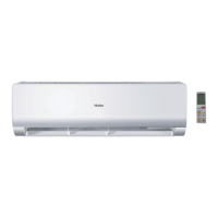
Compressor
Wiring: Compressor Check
CAUTION: Risk of injury. Keep head clear of
terminal area when cover is removed.
Keep head clear of terminal area when cover is
removed.
Check windings rst. If open or grounded, DO
NOT apply power to compressor terminals.
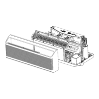
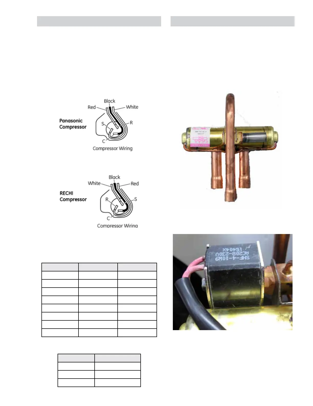
Reversing Valve
*Shown with solenoid removed.
Reversing Valve Solenoid Coil
BTU/Size V Run Start
7K/230V 5.139±7% Ω 6.032±7% Ω
7K/265V 6.747±7% Ω 4.680±7% Ω
9K/230V 3.319±7% Ω 2.635±7% Ω
9K/265V 4.503±7% Ω 3.298±7% Ω
12K/230V 2.526±7% Ω 2.313±7% Ω
12K/265V 3.296±7% Ω 2.505±7% Ω
15K/230V 2.227±7% Ω 3.093±7% Ω
15K/265V 2.840±7% Ω 3.225±7% Ω
Compressor Resistance
Resistance spec is reported as room temperature
readings.
BTU Microfarads
7k 15 uF +/- 5%
9k 30 uF +/- 5%
12k and 15k 30 uF +/- 5%
Capacitor Microfarads
On heat-pump models, the refrigerant ow
direction is controlled by the reversing valve
assembly. In the cooling mode, the main board
supplies line voltage to the solenoid coil, which
causes the valve to switch ow direction. With no
voltage applied to the solenoid coil, the valve will
be in the heating mode.
The solenoid coil attaches to the valve body with
a 5/16-in. hex-head bolt. The 230/208-volt coil
has pink wires and measures approximately 1.5k
ohms.
 Loading...