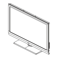
4-4 Remove the Terminal Bracket
Remove the fi ve screw indicated on the
fi gure above by ○
Then put the terminal bracket to the side
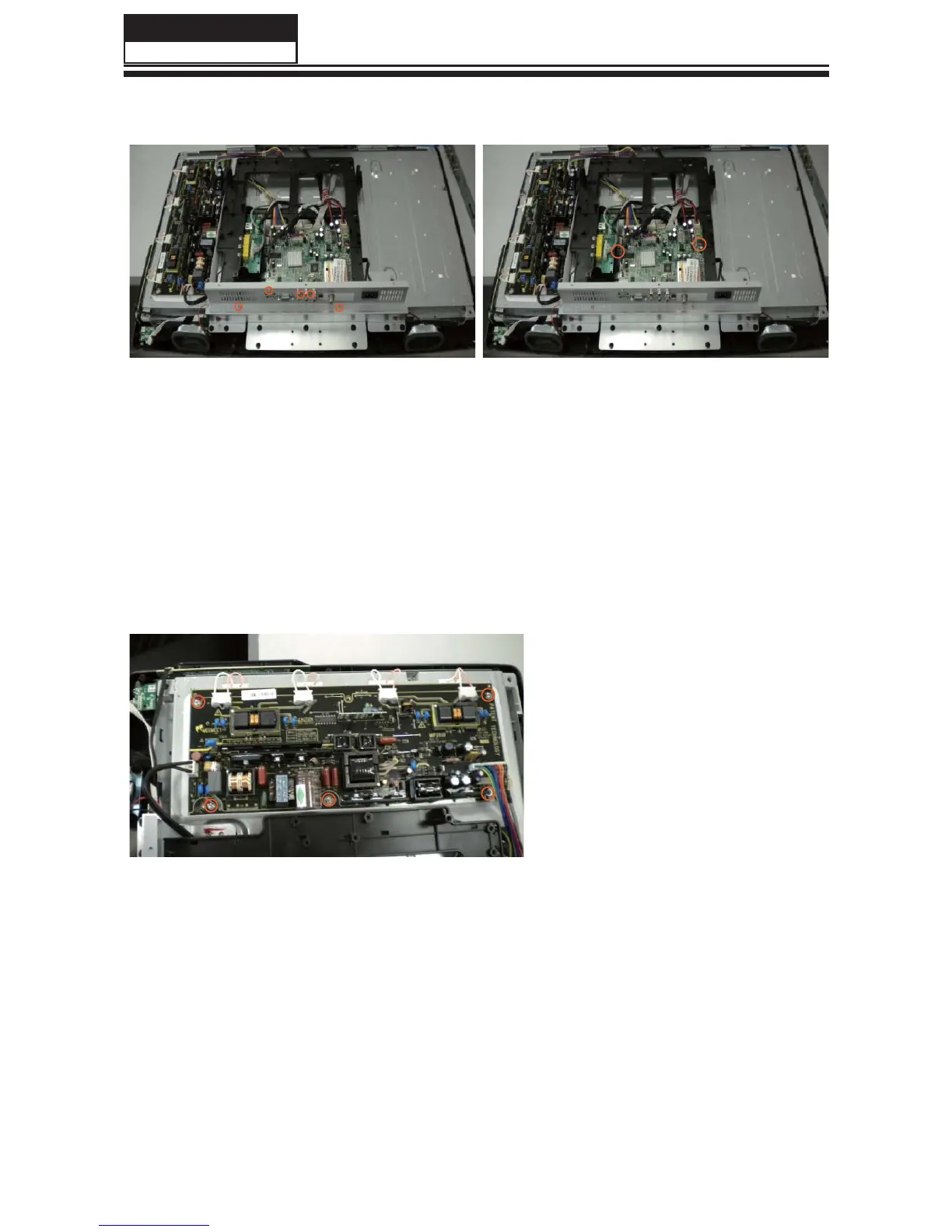
4-5 Remove the power module
Remove the four screw indicated on the
fi gure above by ○
Then remove the power module
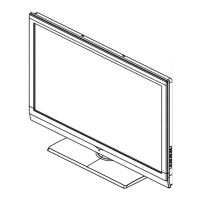
4-6 Remove the Main board
Remove the two screw indicated
on the fi gure above by ○
Disconnected the coupler CN405
J1 CN101 CN406 CN404 CN901
CN601 CN402
Remove the Main board
Service Manual
Model No.:
- 15 -
 Loading...