8
3.2.1 Function Description:
Main Board:
Process signal which incept from exterior equipment,then translate into signal that panel can display.
3.2.2 Connector definition
Main board connector
Power connectors (CN3, CN5)
Notes:
CN3-Pin 3: Backlight on/off:
The system can turn on or turn off the backlight of TFT LCD Panel through the power supply unit path.
CN3-Pin 7: System power on / standby
System board will use this pin to control system power.
CN3-Pin 4: Control the luminance of backlight
The system can generate the PWN signal to control the strength of TFT LCD Panel’s backlight through
this connector.
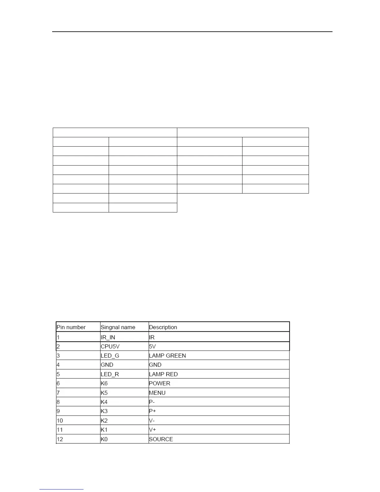
Keypad and remote connector (CN2)
CN3 CN5
Pin number Signal name Pin number Signal name
1 +12V 1 +12V
2 +12V 2 GND
3 BL 3 GND
4 DIM 4 +5V
5 GND 5 STB
6 GND
7 SW
 Loading...