Application Examples
DSO5000P Series Digital Storage Oscilloscope User Manual 56
3. Turn the Trigger Level knob to adjust the trigger level and stabilize video signals.
4. Turn V0 to adjust the line number (NTSC: 0-525 lines).
5. Turn the horizontal SEC/DIV and the vertical VOLTS/DIV knobs to display on the screen a
complete video signal triggering on a video line. See the figure below.
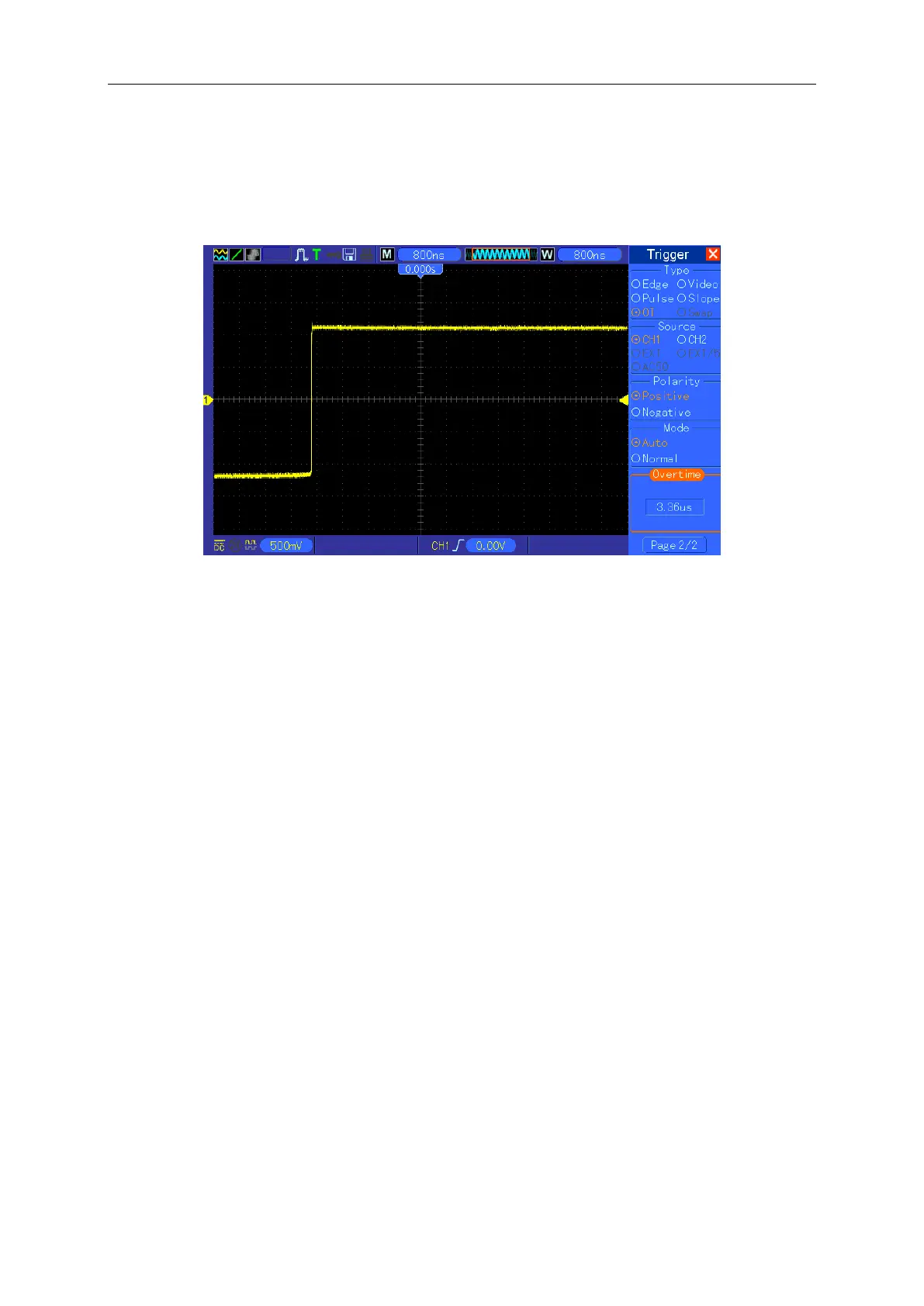
Note: The difference between the overtime and the delay triggers is that the overtime
trigger can identify the pulse you need according to your set time and trigger on any point
of the pulse. In the other word, the overtime trigger occurs based on pulse identification. It
is similar to the > mode of the pulse width trigger, but not the same.
6.10 Example 10: Using Math Functions to Analyze
Waveforms
Using math functions to analyze input waveforms is another advantage of the digital oscilloscope.
For example, you want to get the instantaneous difference between two channel waveforms. By
using the math function of the oscilloscope, you can get a better representation of the waveform
on the screen. To observe this signal, follow the steps below.
1. Set the Probe option attenuation to 10X.
2. Open CH1 and CH2 at the same time, both with the attenuation of 10X.
3. Push the AUTOSET button to trigger a stable waveform.
4. Push the MATH MENU button to see the Math menu.
5. Push the Operation option button and select ‘CH1+CH2’.
6. Turn the horizontal SEC/DIV and the vertical VOLTS/DIV knobs to properly scale the
waveform for easy check.
In addition, the oscilloscope also supports the - and FFT functions. For a detailed analysis on FFT,
 Loading...