Features and Function
HDG2000 Series Arbitrary Waveform Generator 29
Voltage Autoranging
Autoranging is enabled by default and the instrument selects optimal attenuator settings.
Output Control
By default, channel output is disabled at power on to protect other equipment. To enable a
channel's output, see below. When channel output is enabled, the corresponding channel button
is lit.
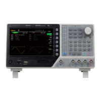
Front Panel:
CH1=CH2: The output signal of CH1 is the same as the output signal of CH2.
CH1+CH2: When thisbutton is on, the output signal of current channel will be the superposition
of CH1 and CH2.
SCPI:
OUTPut<n> ON|OFF,
OUTPut<n>?
Sync Output Signal
A sync output is provided on the front-panel Sync connector. All of the standard output functions
(except DC and noise) have an associated Sync signal. For applications where you may not want
to output the Sync signal, you can disable the Sync connector (Trig Menu->Syns->OFF). The
Sync signal may be derived from either output channel in the instrument.
General Behavior
By default, the Sync signal is derived from channel 1 and is routed to the Sync connector
(enabled).
When the Sync signal is disabled, the output level on the Sync connector is at a logic "low."
For sine, pulse, ramp, square, and triangle waves, the Sync signal is a square wave that is
"high" in the first half of the cycle and "low" in the last half.
The amplitude of Sync signal is not adjustable and fixed at TTL level.
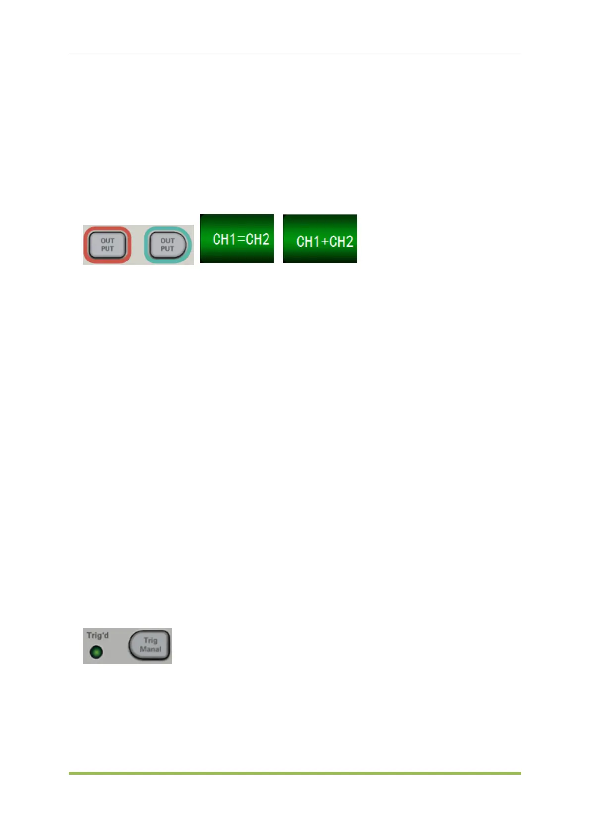
Front Panel:
SCPI:
OUTPut:SYNC:SOURce CH1|CH2
 Loading...