Harman® • PF-120 Installation Manual_R1 • 2014 -___ • 03/1419
3-90-08121i
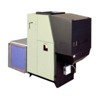
Access Panel
Coveropening
Flexconnector
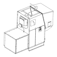
Top
Figure 5.6
Figure 5.7
Assembling Filter Box, Cont’d
5. PlacethetoponthelterboxasshowninFigure5.6.A
tthis
timeallTekscrewscanbeinsertedaroundthelterbox.
Note: Exceptforthe(6)screwsthatattachthebloweraccess
panelinplace.
Thereshouldnotbeanyscrewsprotrudingfromtheboxon
thesidetowardthefurnace.AlsoDONOTputascrewinto
thetopcenterofthelterpanelasascrewinthislocation
willinterferewiththelteraccesscover.
6. Pryoutthetwoknockoutsinthetopoftheboxandinstall
theexconnectorandtheswitch.SeeFigure5.7.Note:
Makesurethatthesetscrewontheexconnectorisnot
pointing toward the furnace end of the box when the
locknutisfullytightened.Thelterboxisnowreadyto
installontothefurnace.
Note: Theblowershouldbemountedonthefurnacebefore
thelterboxforeaseofdistributionblowerinstallation.
Note:Itisbesttowaituntiltheblower,lterbox,andcold
airreturnductworkisinstalledbeforeinstallingthelterand
sidepanel.
7. AftertheFilterBoxisinstalledonthefurnacetheelectrical
wiringneedstobecompleted.Adecisionmustbemade
astowhichspeedsuitesyourinstallation.
Black - Hi
Yellow - Med-Hi
Orange - Med-Low
Red - Low
(Note: the purple wire on the 1638 cfm blower is neutral,
and gets spliced to the white neutral wire.)
8. Installtheaccesspanelcoverbyhookingthelipatthe
bottomofthecoverovertheedgeinthelterbox.Use6
Tekscrewstosecuretheaccesspanel.
 Loading...