Harman® • PF-120 Installation Manual_R1 • 2014 -___ • 03/1421
3-90-08121i
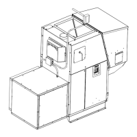
C. Firebrick installation-required
The rebrick is shipped inthe ash pan. It will need to be
placedonthebrickshelfFigure5.12.Itcanbeinstalledwith
eitherfacetothere.Holdthebricklongwaysandslideit
downintotheslotontheshelf.Thereisastopattherearof
theshelftostoptherearwardtravel.Thebrickjustsitson
theshelfintheuprightposition.
Firebrick
Figure 5.12
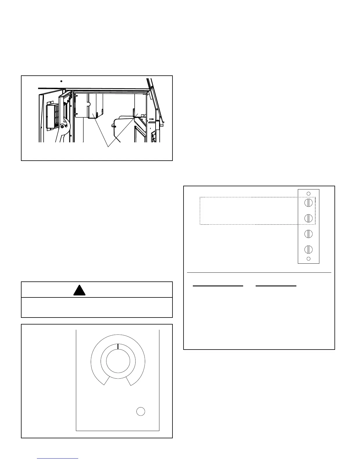
D. Wall Control
TheWallControl(Figure5.13)sendsandreceivesinformation
fromthecontrolboardthrougha4wireDatacomcable.There
isa100’lengthofthiscablesuppliedwiththefurnace.100’
lengthsofthiscablecanalsobeorderedseparately,part#3-
20-02583.Alternately,anyDatacomcable-CAT3-2twisted
pair 24ga solid wire can be acquired at a local electrical
supplyhouse.AlsoanyCAT3-24ga.solidwire2,3,or4pair
cablecanbeusedbecausetheyallhavethesamepaircolor
combinations.Themaximumlengthofwallcontrolwiringis
100feet.
Thefurnaceconnectingpointisa4polescrewterminalblock
onthesideofthehopperjustaroundthecornertotheright
of the control. Follow the wiring instructions on the label
alongsidetheterminalblockFigure5.14.
Figure 5.14
+
-
TH
TH
Orange
Blue
White-Orange
White-Blue
This section is not used on this unit
CAUTION
Withthissmallgaugeofwire,caremustbetakennotto
over-tightentheterminalscrewsthus,breakingthewire.
There are tie-wrap holes in the face of the hopper
approximatelyevery6”tokeepthecablesecureandoutof
theway.
The Wall Control is made to t on a standard wall case
electrical box. It could also be mounted directly to a stud
using2drywallscrews.Ineithercasethescrewsshouldbe
turnedinandtestedforasnugtwhentheWallControlis
sliddownoverthescrews.TheWallControlonlyhangson
thescrewssoagoodtisimportant.
Remove the Wall Control and make the Datacom cable
connections with the UYautosplicersprovided. DO NOT
STRIP THE WIRES.Following the wiring diagram on the
insideoftheWallControlmakeeachsplice.SeeFigure5.14.
Insertthetwomatchingcolorwiresfullyintothetwoholesof
oneoftheUYconnectors.ApairofstandardChannel-lock
pliersworksideallytosqueezetheraisedbuttondownintothe
UYconnectorbody.ExtraUYconnectorscanbepurchased.
Part#3-20-00200
NOTE:Apairofneedlenosepliersmaybehelpfultoinsert
theBLUET-statwiresfullyintotheconnector.Visuallyinspect
toseethatthewiresarefullyinsertedbeforesqueezingthe
UYsplicer.
Figure 5.13
LOW
FUEL
70
7565
60
80
Datacom Cable Wall Control
Orange- Red (+LED)
Blue/White- Blue (Tstat)
Orange/White- WhiteorBlk (-LED)
Blue- Blue (Tstat)
 Loading...