EN FR
11
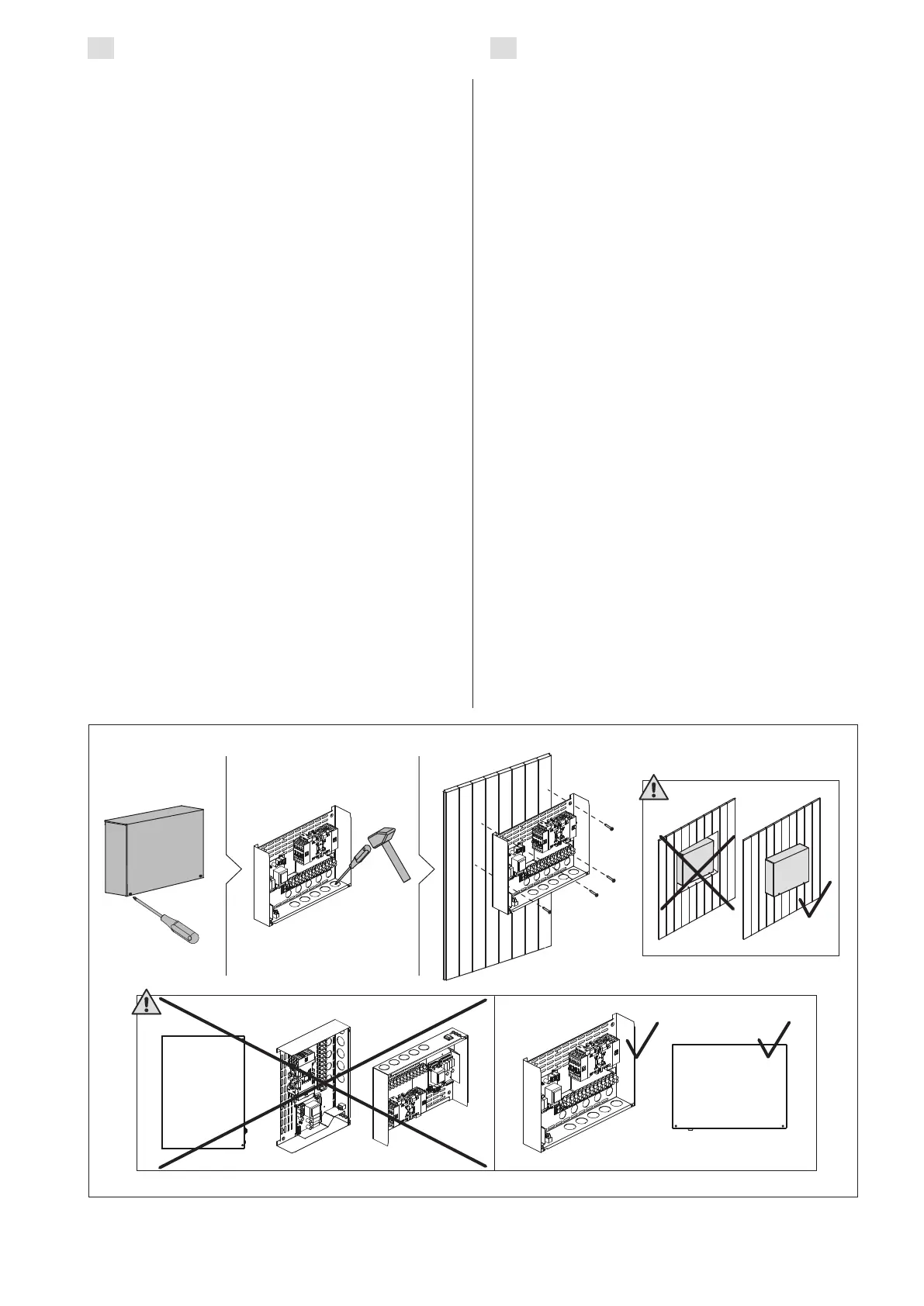
Figure 5. Opening the power unit cover and mounting the unit to a wall
Figure 5. Ouverture du cache du bloc d’alimentation et fixations murales
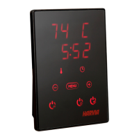
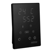
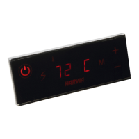
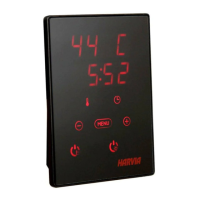
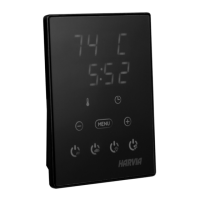
3.1. Installing the Control Panel
The control panel is splashproof and has a low
operating voltage. The panel can be installed in the
dressing room, or in the living quarters. If the panel
is installed in the sauna room, it must be at least 1,5
ft (50 cm) away from the heater and at a maximum
height of one metre from the oor. Figure 4.
Conductor tubing (ø 1”3/16, 30 mm) inside the
wall structure allows you to thread the data cable
hidden within the wall – otherwise the installation
will have to be on the wall surface. We recommend
you to install the control panel embedded in to the
wall and far away from possible splashes.
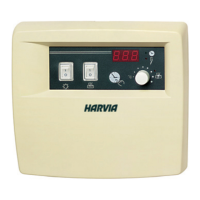
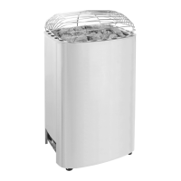
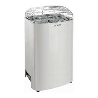
3.2. Installing the Power Unit
Install the power unit to a wall outside the sauna
room, in a dry place with an ambient temperature
more than 32 ºF (0 ºC). See Figure 5 for instructions
on how to open the power unit cover and how to
x the unit to the wall.
Note! Do not embed the control unit into the
wall, since this may cause excessive heating of
the internal components of the unit and lead to
damage. See Figure 5.
3.2.1. Electrical Connections
The heater and control unit may only be connected
to the electrical network in accordance with the
current regulations by a licensed professional
electrician.
Figures 6a and 6b shows the electrical connec-
tions of the power units. For more detailed installa-
tion instructions see The Instructions for Installation
and Use of the selected heater model.
3.1. Installer le tableau de commande
Le panneau de commande est étanche aux écla-
boussures et présente une faible tension de fonc-
tionnement. Il peut être installé dans le vestiaire ou
dans l’habitation. Si le panneau est installé dans
le sauna, il doit être installé à au moins 1,5 pied
(50 cm) du poêle et à une hauteur maximum d’un
mètre par rapport au sol. Figure 4.
Il est possible de faire passer le câble de données
dans le conduit prévu à cet effet (ø 1”3/16, 30 mm)
dans la structure des parois an de le masquer ;
sinon, il doit être installé sur la surface de la paroi. Il
est recommandé d’encastrer le panneau de contrôle
dans le mur éloigné de possibles éclaboussures.
3.2. Installer le bloc d’alimentation
Installez le centre de contrôle sur un mur à
l’extérieur de la cabine, dans un endroit sec à une
température ambiante de > 0 ºC (32 ºF). Consultez
la gure 5 pour connaître les instructions sur le
moyen d’ouvrir le cache du bloc d’alimentation et
savoir comment xer le bloc au mur.
Remarque ! N’encastrez pas le bloc d’alimentation
dans le mur cela pourrait engendrer une surchauffe
des composants internes du bloc et l’endommager.
Voir figure 5.
3.2.1. Raccordement électrique
Le raccordement du poêle et du centre de contrôle
au secteur ne doit être réalisé que par un électricien
professionnel qualifié et conformément aux
règlements en vigueur.
Fig. 6a et 6b montre les connexions électriques du
bloc d’alimentation. Pour obtenir des instructions
d’installation plus détaillées, consultez Les instruc-
tions d’installation et d’utilisation du du modèle de
poêle sélectionné.
 Loading...