EN FR
17
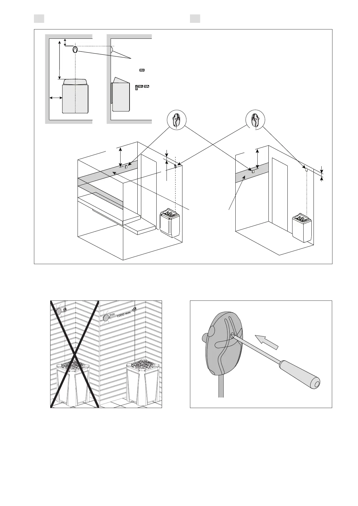
Figure 7. The place of the temperature sensor of the control unit in connection with floor-mounted heaters
Figure 7. Emplacement des capteurs de température par rapport aux poêles en installation au sol
Figure 8. The place of the temperature sensor of the control unit in connection with wall-mounted heaters
Figure 8. Emplacement des capteurs de température par rapport aux poêles en installation murale
Figure 9. Sensor’s minimum distance from an air vent
Figure 9. Distance minimale du capteur avec le
conduit d’air
Figure 10. Reset button of the overheat protector
Figure 10. Bouton de réinitialisation de la sécurité-
surchauffe
Temperature sensor
Capteur de température
3 15/16”
(100 mm)
A
D
4’’/100 mm
4’’/100 mm
min. 20’’/500 mm
max. 28’’/700 mm
min. 20’’/500 mm
max. 28’’/700 mm
Temperature sensor
Capteur de température
Humidity sensor
Capteur d’humidité
Permitted area
for humidity
sensor
Zone autorisée
pour Capteur
d’humidité
A / D = Safety distance of heater
(Check from heater manual)/
Distance de sécurité du poêle
(Vérifier dans le manuel du poêle)
 Loading...